


EW Valve
Instruction Manual
Form 2376
March 2007
5
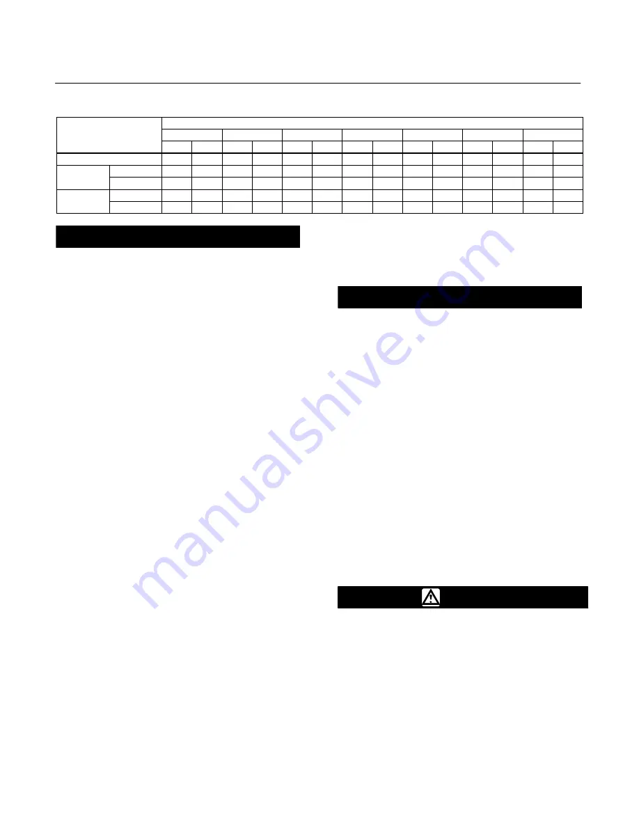
Table 4. Approximate Weights
VALVE SIZE, NPS
END CONNECTION
4X2
6X4
8X4
8X6
10X8
12X6
12X8
END CONNECTION
Kg
Lb
Kg
Lb
Kg
Lb
Kg
Lb
Kg
Lb
Kg
Lb
Kg
Lb
CL300 (flanged only)
84
185
150
330
234
515
284
625
567
1250
500
1102
653
1440
CL600
Flanged
100
220
195
430
272
600
308
680
744
1640
721
1590
857
1890
CL600
Buttwelding
61
135
122
270
177
390
272
600
512
1130
526
1160
658
1450
CL900
Flanged
- - -
- - -
- - -
- - -
- - -
- - -
612
1350
- - -
- - -
- - -
- - -
1361
3000
CL900
Buttwelding
- - -
- - -
- - -
- - -
- - -
- - -
454
1000
- - -
- - -
- - -
- - -
1293
2850
CAUTION
If hoisting the valve, use a nylon sling
to protect the surfaces. Carefully
position the sling to prevent damage
to the actuator tubing and any
accessories. Also, take care to prevent
people from being injured in case the
hoist or rigging slips unexpectedly.
Refer to table 4 for valve assembly
weights. Be sure to use adequately
sized hoists and chains or slings to
handle the valve.
1. Before installing the valve, inspect the valve body
cavity and associated equipment for any damage
and any foreign material.
2. Make certain the valve body interior is clean, that
pipelines are free of foreign material, and that the
valve is oriented so that pipeline flow is in the same
direction as the arrow on the side of the valve.
3. Install the control valve assembly in any
orientation unless limited by seismic criteria.
However, the normal method is with the actuator
vertical above the valve. Other positions may result
in uneven valve plug and cage wear and in improper
operation. With some valves, the actuator may also
need to be supported when it is not vertical. For
more information, consult your Emerson Process
Management sales office.
Note
If installing a valve with small internal
flow passages, such as with
WhisperFlo, Whisper Trim, or Cavitrol
cages, consider installing an upstream
strainer to prevent the lodging of
particles in these passages. This is
especially important if the pipeline
cannot be thoroughly cleaned or if the
flowing medium is not clean.
4. Use accepted piping and welding practices when
installing the valve in the line. For flanged valve
bodies, use a suitable gasket between the valve
body and pipeline flanges.
CAUTION
Depending on valve body materials
used, post weld heat treating may be
required. If so, damage to internal
elastomeric and plastic parts, as well
as internal metal parts is possible.
Shrink-fit pieces and threaded
connections may also loosen. In
general, if post weld heat treating is to
be performed, remove all trim parts.
Contact your Emerson Process
Management sales office for additional
information.
5. With a leak-off bonnet construction, remove the
pipe plugs (keys 14 and 16, figure 21) from the
bonnet to hook up the leak-off piping. If continuous
operation is required during inspection or
maintenance, install a three-valve bypass around the
control valve assembly.
6. If the actuator and valve are shipped separately,
refer to the actuator mounting procedure in the
appropriate actuator instruction manual.
WARNING
Personal injury could result from
packing leakage. Valve packing was
tightened before shipment; however,
the packing might require some
readjustment to meet specific service
conditions. Check with your process
or safety engineer for any additional
measures that must be taken to
protect against process media.
Valves with ENVIRO-SEAL live-loaded packing or
HIGH-SEAL live-loaded packing will not require this


