


EW Valve
Instruction Manual
Form 2376
March 2007
4
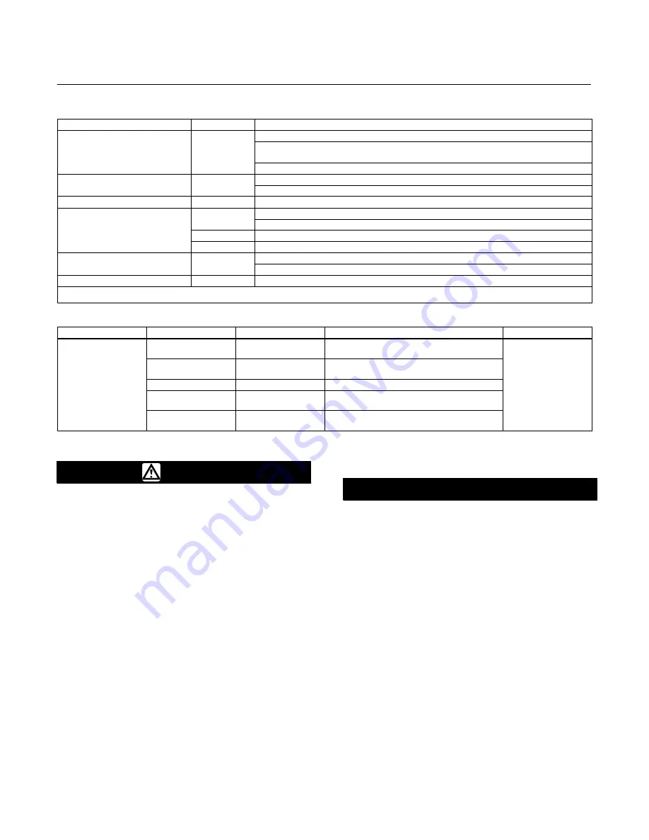
Table 2. Shutoff Classification Per ANSI/FCI 70-2 and IEC 60534-4
Valve Design
Seating
Shutoff Class
EWD
Metal
II (standard)
III (optional for NPS 6x4 through 12x6 valves with optional single graphite piston ring or for
NPS 10x8 and 12x8 valves with optional double piston rings)
IV (optional for NPS 6x4 through 12x8 valves with optional multiple graphite piston rings)
EWS
Metal
IV (standard)
S
V (optional, consult your Emerson Process Management sales office)
EWS
PTFE
VI
EWT with all except
PTFE
Standard Air Test (maximum leakage is 0.05 mL/min/psid/inch port diameter)
p
Cavitrol III cages
V (optional)
Metal
IV (standard)
Metal
V (optional)
(1)
EWT with
Metal
IV (standard)
1-stage Cavitrol III cage
V (optional)
EWT with 2-stage Cavitrol III cage
Metal
V
1. Class V shutoff for Design EWT requires spring loaded seal ring, radius-seat plug, wide-bevel seat ring, and seat lapping. Not available with 8-inch port, quick-opening cage. Not
available with S31600 (316 SST) valve plug and seat ring.
Table 3. Additional Shutoff Classification for C-seal Trim Per ANSI/FCI 70-2 and IEC 60534-4
Valve
Valve Size, NPS
Port Diameter, Inches
Cage Style
Leakage Class
6x4x2.5
2.875
Equal Percentage, Linear, Whisper I,
Cavitrol III (2-stage)
Design EWD
6x4
8x4
4.375
Equal Percentage, Linear, Whisper I,
Cavitrol III (1-stage)
V (for port
diameters from 2 875
Design EWD
(CL300 CL600)
8x6 and 12x6
5.375
Whisper III (A3, B3, D3, D3), Cavitrol III (2-stage)
diameters from 2.875
through 8-inch with
(CL300, CL600)
8x6
12x6
7
Equal Percentage, Linear, Whisper I,
Cavitrol III (1-stage)
through 8-inch with
optional C-seal trim)
10x8
12x8
8
Equal Percentage, Linear, Whisper I,
Cavitrol III (1-stage)
Installation
WARNING
Always wear protective gloves,
clothing, and eyewear when
performing any installation operations
to avoid personal injury.
Personal injury or equipment damage
caused by sudden release of pressure
or bursting of parts may result if the
valve assembly is installed where
service conditions could exceed the
limits given in table 1 or on the
appropriate nameplates. To avoid such
injury or damage, provide a relief valve
for overpressure protection as
required by government or accepted
industry codes and good engineering
practices.
Check with your process or safety
engineer for any additional measures
that must be taken to protect against
process media.
If installing into an existing
application, also refer to the WARNING
at the beginning of the Maintenance
section in this instruction manual.
CAUTION
When ordered, the valve configuration
and construction materials were
selected to meet particular pressure,
temperature, pressure drop and
controlled fluid conditions.
Responsibility for the safety of
process media and compatibility of
valve materials with process media
rests solely with the purchaser and
end-user. Since some body/trim
material combinations are limited in
their pressure drop and temperature
ranges, do not apply any other
conditions to the valve without first
contacting your Emerson Process
Management sales office.
Before installing the valve, inspect the
valve and pipelines for any damage
and any foreign material which may
cause product damage.


