


Model A31A
7
Table 5. Hex Head Screw, Stud Bolt and Cap Screw Data
(1)
Valve
Size,
No. of Cap Screws
No. of Stud Bolts
Size-Dia. Inch & Thread
Length of Cap
Screws,Inch
Length of Stud
Bolts,Inch
Size,
Inches
Class 150
Class 300
Class 150
Class 300
Class 150
Class 300
Class 150
Class 300
Class 150
Class 300
Single-Flange Style
(2)
14
24
40
- - -
- - -
1-8
1-1/8-8
2-3/4
3-1/2
- - -
- - -
16
32
40
- - -
- - -
1-8
1-1/4-8
3
3-3/4
- - -
- - -
18
32
48
- - -
- - -
1-1/8-8
1-1/4-8
3-1/4
4
- - -
- - -
20
40
48
- - -
- - -
1-1/8-8
1-1/4-8
3-1/2
4
- - -
- - -
24
40
48
- - -
- - -
1-1/4-8
1–1/2-8
3-1/2
4-1/2
- - -
- - -
Wafer-Style
14
- - -
8
12
16
1-8
1-1/8-8
- - -
3-1/2
9-1/2
12
16
- - -
8
16
16
1-8
1-1/8-8
- - -
3-3/4
10
13-1/2
18
- - -
8
16
16
1-1/8-8
1-1/4-8
- - -
4
11
13-3/4
20
- - -
8
20
20
1-1/8-8
1-1/4-8
- - -
4
12
14-1/2
24
- - -
8
20
20
1-1/4-8
1-1/2-8
- - -
4-1/2
14
16-1/2
1. Thread engagement in accordance with ANSI B31.3-1976 “Chemical Plant and Petroleum Refinery Piping”.
2. Bolting lengths are based on installation of valve between standard raised face flanges and utilizing flange gaskets with a final compression thickness of 1/8 inch. When gaskets
used have a final compression thickness of less than 1/8 inch, reduce bolting lengths shown by 1/4 inch.
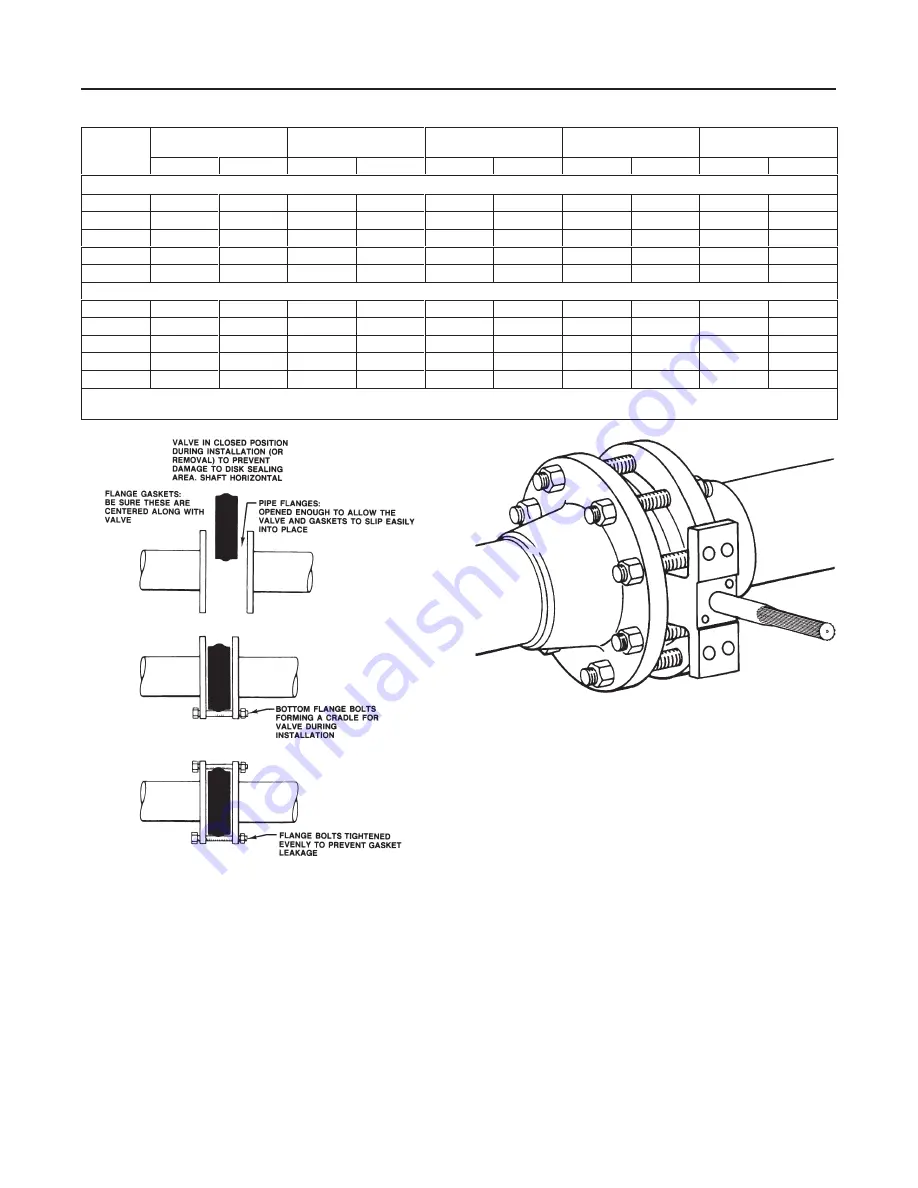
Figure 4. Proper Installation Steps
B2263-1/IL
Adjusting the Actuator Travel Stops or
Travel
Key number locations are shown in figure 9, unless
otherwise noted.
1. Refer to the actuator instruction manual to locate
the actuator travel stop that control the closed position
of the valve disk (key 2). When adjusting the travel
stop or travel, make sure that the disk is from 0 to
0.030 inch (0 to 0.76 mm) away from the internal stop
A5557/IL
Figure 5. Properly Installed Wafer-Style Valve
in the valve body. This adjustment is necessary to be
certain that the actuator output torque is fully absorbed
by the actuator travel stop or by the actuator. The in-
ternal travel stop in the valve body should not absorb
any of the actuator torque.
2. Before installing the valve/actuator assembly in the
process line, cycle the valve several times to be sure
the valve disk returns to the proper position.
Installing the Valve
The maximum allowable inlet pressures for Model
A31A valves are consistent with the applicable ANSI
pressure/temperature ratings except where limited by
the material capabilities as shown in table 2 or figure
3.
Refer to table 5 for the quantity and size of line bolting
required to install the valve in the pipeline.


