


249W Level Sensor
Instruction Manual
Form 5729
May 2006
10
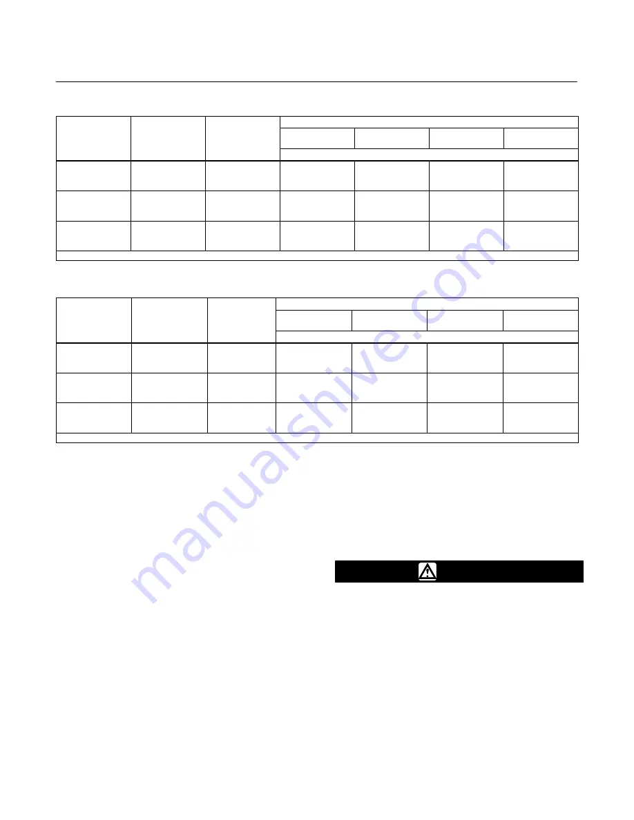
Table 2. Recommended Bolt Torque for Typical Lubricants (3-Inch Flanges)
Bolt and Nut
Material
Bolt Size
Mating Flange
Class
Lubricant
Fisher NCF2
(1)
Coating
Molykote
R
321R
Lubriplate
R
Mag-1
Never-Seez
R
Nickel Special
Torque, N
S
m (lbf
S
ft)
SA193-B7
5/8 - 11
3/4 - 10
3/4 - 10
CL150
CL300
CL600
431
±
62 (97
±
14)
667
±
98 (150
±
22)
667
±
98 (150
±
22)
431
±
62 (97
±
14)
667
±
98 (150
±
22)
667
±
98 (150
±
22)
556
±
84 (125
±
19)
845
±
124 (190
±
28)
845
±
124 (190
±
28)
534
±
80 (120
±
18)
801
±
133 (180
±
30)
801
±
133 (180
±
30)
SA193-B7M
5/8 - 11
3/4 - 10
3/4 - 10
CL150
CL300
CL600
431
±
44 (97
±
10)
689
±
71 (155
±
16)
689
±
71 (155
±
16)
431
±
44 (97
±
10)
689
±
71 (155
±
16)
689
±
71 (155
±
16)
556
±
58 (125
±
13)
890
±
89 (200
±
20)
890
±
89 (200
±
20)
534
±
53 (120
±
12
845
±
84 (190
±
19)
845
±
84 (190
±
19)
SA193-B8M CL2
5/8 - 11
3/4 - 10
3/4 - 10
CL150
CL300
CL600
Not applicable
418
±
62 (94
±
14)
689
±
102 (155
±
23)
689
±
102 (155
±
23)
534
±
80 (120
±
18)
890
±
133 (200
±
30)
890
±
133 (200
±
30)
511
±
67 (115
±
15)
845
±
124 (190
±
28)
845
±
124 (190
±
28)
1. Torque values for NCF2 without additional lubricant are equal to Molykote 321R
Table 3. Recommended Bolt Torque for Typical Lubricants (4-Inch Flanges)
Bolt and Nut
Material
Bolt Size
Mating Flange
Class
Lubricant
Fisher NCF2
(1)
Coating
Molykote 321R
Lubriplate Mag-1
Never-Seez
Nickel Special
Torque, N
S
m (lbf
S
ft)
SA193-B7
5/8 - 11
3/4 - 10
7/8 - 9
CL150
CL300
CL600
431
±
62 (97
±
14)
667
±
98 (150
±
22)
1022
±
102 (230
±
23)
431
±
62 (97
±
14)
667
±
98 (150
±
22)
1022
±
102 (230
±
23)
556
±
84 (125
±
19)
845
±
124 (190
±
28)
1289
±
129 (290
±
29)
534
±
80 (120
±
18)
801
±
133 (180
±
30)
1222
±
122 (275
±
28)
SA193-B7M
5/8 - 11
3/4 - 10
7/8 - 9
CL150
CL300
CL600
431
±
44 (97
±
10)
689
±
71 (155
±
16)
1022
±
102 (230
±
23)
431
±
44 (97
±
10)
689
±
71 (155
±
16)
1022
±
102 (230
±
23)
556
±
58 (125
±
13)
890
±
89 (200
±
20)
1289
±
129 (290
±
29)
534
±
53 (120
±
12
845
±
84 (190
±
19)
1222
±
122 (275
±
28)
SA193-B8M CL2
5/8 - 11
3/4 - 10
7/8 - 9
CL150
CL300
CL600
Not applicable
418
±
62 (94
±
14)
689
±
102 (155
±
23)
956
±
96 (255
±
96)
534
±
80 (120
±
18)
890
±
133 (200
±
30)
1133
±
114 (255
±
26)
511
±
67 (115
±
15)
845
±
124 (190
±
28)
1111
±
111 (250
±
25)
1. Torque values for NCF2 without additional lubricant are equal to Molykote 321R
Note
In the next step, if mounting the wafer
body on a displacer cage and a flange
adaptor is required, install the flange
adaptor instead of the blind flange.
5. Refer to figure 11. Place a second seal on top of
the wafer body. Place a blind flange on the wafer
body so that the holes in the blind flange align with
the holes in the connecting flange.
6. Refer to figure 12. Secure the wafer body
between the blind flange and connecting flange by
inserting the remaining studs and nuts. Tighten the
nuts just enough to hold the wafer body in place.
7. Remove the nut from the stud that was used in
step 2. Reinsert the stud so it passes through the
holes in the blind flange and connecting flange.
Thread the nut back onto the stud.
8. Tighten all nuts in a crisscross fashion to the
torque recommended in tables 2 or 3.
Maintenance
Sensor parts are subject to normal wear and must
be inspected and replaced as necessary. The
frequency of inspection and replacement depends
upon the severity of service conditions.
WARNING
Avoid personal injury or property
damage resulting from the sudden
release of pressure. Before performing
any maintenance procedure:
D
Always wear protective clothing,
gloves, and eyewear.
D
Relieve any process pressure in
the process vessel where the Type
249W sensor is installed.
D
Drain the process liquid from the
process vessel.


