background image

ROBO TX ElectroPneumatic

COMPUTING

13

Ball obstacle course  
with vacuum picker arm

With this model the vacuum picker arm automati-
cally returns balls from the end to the start of an 
obstacle course. Build the model according to 
the assembly instructions and wire the electrical 
and pneumatic components according to the 
circuit diagram. During assembly pay attention to 
 accuracy when installing the parts, connecting the hoses 
and wiring the electrical components. This eliminates the need for 
trouble-shooting when you put the model into operation.

Task 1 - Return a ball - ROBO Pro Level 2 

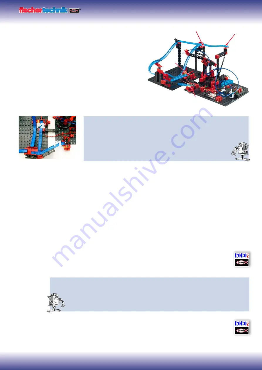
A ball is to be returned at one of the two ends of obstacle course P1 or P2 by the 
vacuum picker arm. The two light barriers are checked to determine where the ball 
is located. After picking up, the ball is transported to position 3 on the obstacle 
course and put down. The ball rolls to the gate where it is guided to one of 
the two final paths. The program is intended to run as a continuous loop.

Tips


As with the previous programming tasks, it is necessary to consider the sequence you want. Also con-
sider which parts of the program will need to be written in a subprogram.

Switch on the compressor and lens tip lamps for the light barriers (2 sec. time delay)


Start the model and position the robot arm at the start position - Check sensor I1, motor direction of 


rotation: Counterclockwise
Check the two light barriers


Pick up the balls


Transport to set-down location P3 and set down balls - pulse counter


Return to light barrier check to see if new balls are present


You can call a finished example program for this task with this symbol.

Task 2 - Both obstacle courses - ROBO Pro Level 2 

The light barrier check tells the robot where a ball is located so that the robot can transport the ball 

to the start of the track. If the ball is at the end of the front track (P1), it should be put down at 

position P3. If the ball is at the end of the rear track (P2), it should be put down at position P4.

You can call a finished example program for this task with this symbol.

Ends of obstacle courses

P2

P1

ball obstacle course_1.rpp

ball obstacle course_2.rpp

P3

P4

P2

P1

Содержание COMPUTING ROBO TX ElectroPneumatic

Страница 1: ......

Страница 2: ... storing compressed air diaphragm pump as compressor 5 Switching compressed air solenoid valves 6 Interaction of electrical and pneumatic circuits 6 ROBO Pro control software 7 ROBO TX Controller 7 Compressed air motor 8 Programming 9 Color sorting robot 10 Sensors 10 Sensors and actuators 11 Color recognition subprogram 12 Ball obstacle course with vacuum picker arm 13 Variables 14 Pinball machin...

Страница 3: ...et the challenge of the next task and so forth step for step So don t be timid we will plunge into the fischertechnik Computing World together and then go on to more complex tasks Now we wish you a great deal of fun and success experimenting with the ROBO TX ElectroPneumatic set Your team from About this Activity Booklet This PDF Activity booklet has a few features not present in the printed bookl...

Страница 4: ... everywhere For example on assem bly lines various parts are put together to form assemblies and the function is checked goods are sorted and packed Principles of pneumatics Air can be used for different purposes in technology For example wind drives gigantic windmills to generate electrical power Pneumatics uses air to generate motion and transfer forces You are certainly familiar with at least o...

Страница 5: ...pressure is bars or Pascals You can remember the following equation for this Pressure force area or p F A From this equation you can see that the pressure depends on the force exerted on a round surface in the cylinder Generating and storing compressed air diaphragm pump as compressor The diaphragm pump included in the construction set supplies the compressed air required for you to control the in...

Страница 6: ...gh connection A to the cylinder When voltage is not applied the core is pressed upward by the spring 3 and the valve is closed When the valve is closed connection A is connected to the vent R This is important to allow the air to escape from the cylinder The connections are always designated as follows in pneumatics P Compressed air connection A Connection to cylinder R Vent Interaction of electri...

Страница 7: ...ut having to learn a programming language For the ROBO TX ElectroPneumatic construction set you need ROBO Pro version 3 1 3 or higher If you have an older version of the software it will be automatically updated when you install the ROBO TX ElectroPneumatic CD ROBO TX Controller The ROBO TX Controller is the most important component in the model It controls the actuators motors lights valves and e...

Страница 8: ...d in the assembly instructions in circuit diagram A Task 1 Manual control with pushbutton Press the button and observe the model What makes the wheel turn and how As you can see each time you press the button the solenoid valve switches and the cylinder extends This causes the wheel to rotate half a turn When you release the button the wheel rotates another half turn This is accomplished by the re...

Страница 9: ... the information closed open used to control the valve and cylinder The operating display can be cleared with the New button In the Level selection window switch to level 1 All the commands required for this task are present in the Element group selection window However the ROBO Pro help is also very valuable here Each program always starts with the Little green traffic light man Then the individu...

Страница 10: ...nents according to the circuit diagram During assembly pay attention to accuracy when installing the parts connecting the hoses and wiring the electri cal components This eliminates the need for trouble shooting when you put the model into operation Sensors With this model you become familiar with new components such as those used in industrial equipment This includes the vacuum picker arm with su...

Страница 11: ...tion Pay attention to the polarity when connecting the phototransistor to the power supply Red positive Lens tip lamp This is an incandescent bulb with built in lens to focus the light It is required to build a light barrier The lens tip lamp can be recognized by its gray base Electric motor The direct current motor converts electrical energy into mechanical energy This results in the rotational m...

Страница 12: ...m for this task with this symbol Color recognition subprogram In addition to the main program you can also create subprograms in ROBO Pro These serve to keep your program structure clear once written subprograms can also be copied into other applications Information on what subprograms are and how they can be used is given in the ROBO Pro help in Chapter 4 It is important that you switch to level ...

Страница 13: ...continuous loop Tips As with the previous programming tasks it is necessary to consider the sequence you want Also con sider which parts of the program will need to be written in a subprogram Switch on the compressor and lens tip lamps for the light barriers 2 sec time delay Start the model and position the robot arm at the start position Check sensor I1 motor direction of rotation Counterclockwis...

Страница 14: ... they should also be picked up alternately You can meet these requirements by supplementing the program Tips So called variables help to solve this problem Information on what variables are and how they can be used is given in the ROBO Pro help in Chapter 5 It is important that you switch to level 3 in ROBO Pro Here is the solution Define a variable Pos1 Pos4 for each of the 4 positions P1 P2 P3 a...

Страница 15: ...ght side of the model This works according to the same principle as a real pinball machine l The two buttons at the left and right lower edges serve for electrical control of the two valves for the built in cylinders These control the two flipper arms A light barrier detects when a ball drops through the middle gap or runs past an incorrectly positioned flipper arm This light barrier also serves l...

Страница 16: ... a little help Switch on compressor 03 light outputs O6 and O7 for light barriers Shoot in ball manually Check flipper buttons I1 left and I2 right actuate valves at 04 and 05 Check and evaluate color sensor at I8 Check and evaluate light barriers at I3 and I4 Output points earned and balls played on display End of game reset outputs 03 06 and 07 to zero Start new game with OK button right display...

Страница 17: ... and simultaneously counts how many times the light barrier is interrupted during this time The more times you quickly shoot the ball through the light barrier the more points you get Light barrier subprogram The color sensor allows you to get more points when the ball passes closer to the sensor Do you have any other ideas Use your imagination Enjoy programming and playing with your pinball machi...

Страница 18: ...ElectroPneumatic ElectroPneumatic ...

Отзывы: