FISCHER Mess- und Regeltechnik GmbH
Assembly | 3
BA_EN_MA15_ATEX
15 / 36
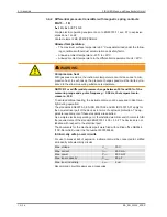
3.4.3 Differential pressure transmitter with inductive contacts
MA15 … 1C
II 2G Ex h IIC T4 Gb
II 2D Ex h IIIC T95°C Db
Explosive areas Zone 1 and 2, and 21 and 22, risk from gases and dry dust.
Contact element: KE ## I ## 0C0H2
Allowed temperatures:
• The maximum surface temperature 95 °C was determined under the follow-
ing conditions without dust accumulation and safety factor.
• Allowed ambient temperature: -20°C to +60°C.
• Allowed medium temperature in the differential measurement unit < 85°C.
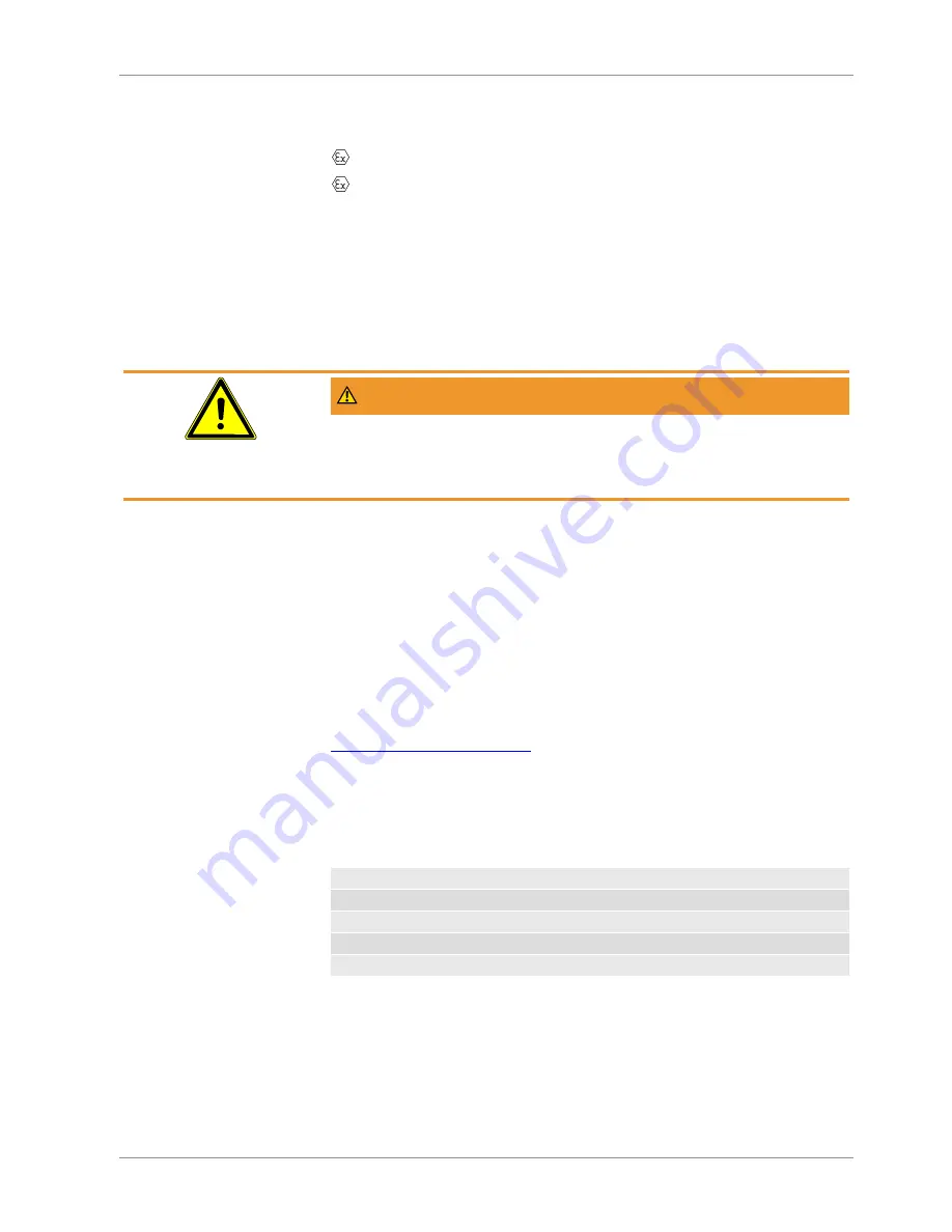
WARNING
Compression heat
With gaseous mediums, the instrument temperature can increase due to com-
pression heat. In such cases, the pressure change speed must be limited or re-
duced to the allow measuring substance temperature.
NOTICE! For a differential pressure change between 10% and 90% of the
measuring range and a pulse frequency < 0.06 Hz, the temperature in-
crease is <10K.
To avoid additional heating, the instruments may not be exposed to direct sun-
light during operation!
The standards EN60079-0, EN 60079-31, EN ISO 80079-36 and EN ISO
80079-37 apply for the non-electrical part of the devices in terms of explosion
protection. The applicable requirements of these standards are satisfied.
The installed inductive proximity switches of the type SJ2-N (106575) are EC
type-tested with the certificate PTB 99 ATEX 2219 X. The type of the installed
proximity switch is stated on the type plate. The manufacturer is Fuchs
GmbH. For more information about proximity switches, please visit the website
https://www.pepperl-fuchs.com
.
The documents for the mechanical part were filed with notified office NB0044
(TÜV-Nord-Cert) under the file number 8000389448.
Intrinsically safe power circuits
For use in areas at risk of explosion, instruments must be connected to certified,
intrinsically safe electricity circuits.
Max. voltage
U
max
16 V
Max. current
I
max
25 mA
Max. power
P
max
64 mW
Max. inner capacity
C
i max
30 nF
Max. inner inductivity
L
i max
100 µH
Recommend circuit breakers see accessories
Содержание MA15F ... A Series
Страница 31: ...FISCHER Mess und Regeltechnik GmbH Attachments 8 BA_EN_MA15_ATEX 31 36 Fig 18 CE_DE_MA15F_1B_Page2...
Страница 32: ...8 Attachments FISCHER Mess und Regeltechnik GmbH 32 36 BA_EN_MA15_ATEX Fig 19 CE_DE_MA15F_1C_Page1...
Страница 33: ...FISCHER Mess und Regeltechnik GmbH Attachments 8 BA_EN_MA15_ATEX 33 36 Fig 20 CE_DE_MA15F_1C_Page2...
Страница 34: ...8 Attachments FISCHER Mess und Regeltechnik GmbH 34 36 BA_EN_MA15_ATEX Fig 21 CE_DE_MA15F_2D_Page1...
Страница 35: ...FISCHER Mess und Regeltechnik GmbH Attachments 8 BA_EN_MA15_ATEX 35 36 Fig 22 CE_DE_MA15F_2D_Page2...
Страница 36: ...8 Attachments FISCHER Mess und Regeltechnik GmbH 36 36 BA_EN_MA15_ATEX Fig 23 CE_DE_MA15F_0A...


