


DFLEX Assembly instructions |
22
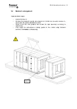
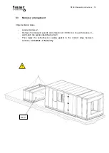
-
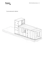
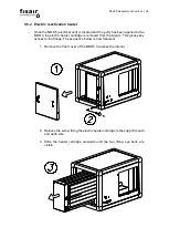
Insert the aforementioned tubes on module -3- about 80mm from the basic unit
(module -4- ) and immediately below section S5-4.
-
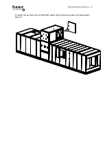
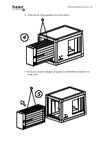
Place the steam battery (module -5- ) on the tubes slightly separated from the
basic unit, so as not to damage the previously applied sealant.
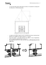
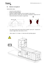
-
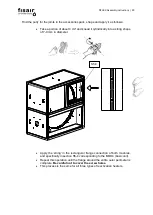
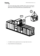
Move the steam battery (module -5-) towards the basic unit by matching the
screw holes for the junction flanges of section S5-4.
-
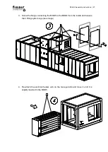
Find the correct screws in the bag marked S5-4 and secure them to attach the
flanges of module -4- to module -5-. The next step is to place the fibre glass
insulation around the junction between these two modules.
Содержание DFLEX 1100
Страница 2: ...DFLEX Assembly instructions 2...
Страница 16: ...DFLEX Assembly instructions 16 The following result is obtained...
Страница 29: ...DFLEX Assembly instructions 29 DFLEX 1100 400V 5...
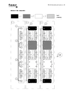
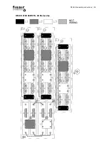
Страница 30: ...DFLEX Assembly instructions 30 DFLEX 1100 440 480V NOT WIRING...
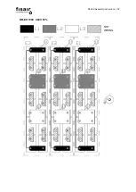
Страница 31: ...DFLEX Assembly instructions 31 DFLEX 1300 400V 5...
Страница 32: ...DFLEX Assembly instructions 32 DFLEX 1300 460V 5 NOT WIRING...
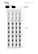
Страница 33: ...DFLEX Assembly instructions 33 DFLEX 1700 400V 5...
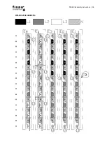
Страница 34: ...DFLEX Assembly instructions 34 DFLEX 2100 400V 5...
Страница 35: ...DFLEX Assembly instructions 35 DFLEX 2100 460V 5 48 Elementos NOT WIRING...
Страница 36: ...DFLEX Assembly instructions 36 DFLEX 2100 460V 5 45 elements Requires SSR in E4 NOT WIRING...
Страница 37: ...DFLEX Assembly instructions 37 8 Finally replace and close the front cover of the MOD5 electrical unit...
Страница 49: ...DFLEX Assembly instructions 49 Finally the different cable connections should be as shown below...


