background image


STEP 1:


If filter media is already in the media tank, proceed to step 3.  If media is shipped 
separately, remove the fill port cap by turning it counter-clockwise with the wrench 
provided. After fill port cap is removed also remove the filter screen inside the fill port. 
Add media through the fill port using a funnel. Do not overfill the tank.  At least 18" of 
freeboard (empty space) is required at the top of the media tank.  More media may have 
been provided than required for initial fill.  Save any extra media for future replenishment. 
Clean any media out of fill port threads. Do not replace the fill port cap yet. 


STEP 2:


Place carbon tank (tank with carbon and fill port) on the 

LEFT

 side with the inlet and 

outlet pointing right. Place the softener tank on the 

RIGHT

 side with inlet and outlet 

pointing left. Attach the control valve assembly to the front inlet/outlet openings of the 
filter and softener tanks. Attach straight pipe adapter to back inlet/outlet openings of the 
two tanks.  Hand tighten union nuts. Do not over tighten.   


STEP 3: 

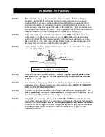
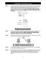
Use clips and screws provided and attach bypass valve to the inlet/outlet of the control 
valve. See figure 1 below.   


STEP 4:


Place unit at desired installation position.  

DO NOT plug into electrical outlet at this 

time (see STEP 12 on page 6).  DO NOT put salt in the brine tank at this time (see 
STEP 16 on page 7). 

 
STEP 5:


Shut off water at main supply.  Relieve pressure by opening nearest faucet.  On private 
well systems, turn off power to pump and drain pressure tank.  

SHUT OFF POWER OR 

FUEL SUPPLY TO WATER HEATER


STEP 6: 

Cut main supply line as required


to fit plumbing to inlet and outlet of bypass valve.  

DO 

NOT PLUMB INLET AND OUTLET BACKWARDS

.  Piping should be supported.  Do not 

apply heat to any fitting attached to the bypass or control valve. 


STEP 7: 

Use polyethylene drain line tubing provided (

NO VINYL TUBING

) to run drain line from 

control valve discharge fitting to floor drain or sump pit capable of handling the backwash 
rate of the unit. 

DISCHARGE END OF THE DRAIN LINE MUST BE FIRMLY SECURED!  

There must be an air gap at the end of the drain line to prevent siphoning of waste water 
and meet plumbing code. 

Total length of drain line should be 15’ or less.  AVOID 

OVERHEAD DRAINS 

.   


Installation Instructions  

FIGURE 1:  Top View of Control Valve 

OUT 

RETAINER CLIPS 

DRAIN ELBOW 

ELBOW LOCKNG CLIP 

CONTROL VALVE 

METER MODULE 

BYPASS  
IN SERVICE  
POSITION 

IN 

Содержание CITY Series

Страница 1: ...LC 12630 US Highway 33 N Churubusco IN 46723 Phone 260 693 1972 Fax 260 693 0602 CITY Series Instruction Manual 190829 docx CITY Series Water Softening and Filter System Installation Instructions and Owner s Manual ...

Страница 2: ...s Valve Page 6 Media Replacement Page 7 CITY Series Programming Page 8 Specifications Page 10 Component Parts Breakdown List Page 11 CITY Series Control Valve Breakdown Page 12 CITY Series Control Valve Parts List Page 13 Troubleshooting Page 14 Ten Year Limited Warranty Page 16 Table of Contents ...

Страница 3: ...nsidered to be soft water pH A measurement of the acidity of the water pH is reported on a scale from 0 to 14 Neutral water has a pH of 7 0 lower values indicate acidic water If your pH is below 6 8 you may consider installing an acid neutralizer before the water softener to elevate the pH Iron A naturally occurring metallic element Iron levels in excess of 0 3 milligrams liter mg l combine with o...

Страница 4: ...flow rate refer to unit specifications 3 All water conditioning equipment should be installed prior to the water heater Water temperatures exceeding 100 F can damage the internal components of the control valve and filter tank Install with at least 10 of pipe before the water heater to prevent thermal damage to the equipment An expansion tank may need to be installed in the line to the water heate...

Страница 5: ...to the inlet outlet of the control valve See figure 1 below STEP 4 Place unit at desired installation position DO NOT plug into electrical outlet at this time see STEP 12 on page 6 DO NOT put salt in the brine tank at this time see STEP 16 on page 7 STEP 5 Shut off water at main supply Relieve pressure by opening nearest faucet On private well systems turn off power to pump and drain pressure tank...

Страница 6: ... DRAIN LINE FROM SOFTENER CONTROL VALVE TO BRINE TANK OVERFLOW DO NOT CONNECT BRINE TANK DRAIN LINE TO THE SOFTENER DRAIN LINE STEP 10 Place bypass valve in the Bypass position refer to Figure 3 below Open main supply valve or turn on power to pump on private well systems STEP 11 Fill the filter tank with water through the fill port using a garden hose or bucket Replace the fill port screen and fi...

Страница 7: ...g If the water level does not drop refer to section 8 of Troubleshooting STEP 16 Fill the brine tank with water softener salt STEP 17 Advance the unit to the fast rinse cycle by pressing the center ADVANCE button briefly and allow the regeneration to complete automatically STEP 18 Check for leaks and correct as necessary STEP 19 Turn power or fuel supply back on to water heater STEP 20 Set the cur...

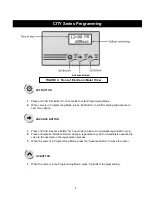
Страница 8: ... to initiate an immediate regeneration cycle 2 Press and release Advance Button during a regeneration cycle to immediately advance the valve to the next step in the regeneration process 3 When the valve is in Programming Mode press the Advance Button to move the cursor UP BUTTON 1 When the valve is in the Programming Mode press Up Button to adjust setting CITY Series Programming Advance Button FIG...

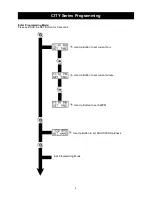
Страница 9: ... Press and Hold the SET Button for 5 seconds CITY Series Programming Use Up Button to set current hour Use Up Button to set current minute Use Up Button to set AM PM Use Up Button to set ADJUSTED Hardness Exit Programming Mode ...

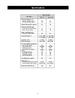
Страница 10: ...fix S suffix 1 1S suffix Injector color Draw Rinse gpm 2 Blue 0 56 0 84 2 Blue 0 56 0 84 Factory Programming Settings Day Override Setting 14 14 Regeneration Time 2 00 AM 2 00 AM Default size setting OFF OFF Regenerate after capacity grains 12 000 24 000 Backwash minutes 8 9 Brine Draw minutes 55 60 Fast Rinse minutes 10 10 Brine Refill minutes 3 5 Total Water Used gallons 90 123 Dimensions in Min...

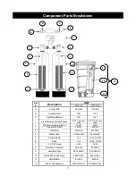
Страница 11: ...en for Fill Port FPS101 FPS101 3 Distributor D100S 48 D100S 54 4 Media Tank MTP0948GR MTP1054GR 5 Carbon Media A10 1 A10 1 A05P 6 Resin H10 1 H10 1 H05P 7 X 1 8 Gravel QC20 QC20 8 Dual Tank Connector DTC204 8 DTC204 8 9 Overflow Fitting BT OVERFLO BT OVERFLO 10 Safety Brine Valve Assy SBV33ASSY SBV33ASSY 11 Salt Platform BTSG18 BTSG18 12 Brine Tank Assembly BTSQ1833ASSY BTSQ1833ASSY Component Part...

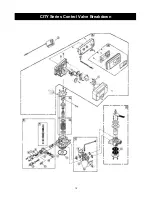
Страница 12: ...12 CITY Series Control Valve Breakdown ...

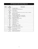
Страница 13: ...el Bypass Valve 1S Suffix Models 1 42349 Motor 24v 60hz 2 RPM 2 NE TRANS Transformer 110v Input 24v Output 3 13304 O Ring Distributor 121 4 12281 O Ring Tank 338 5 10914 2 Injector Throat 2 Blue 6 10227 Injector Screen 7 10913 2 Injector Nozzle 2 Blue 8 13303 O Ring 021 9 12089 Flow Control Washer 3 0 GPM 12091 Flow Control Washer 4 0 GPM 10 NE DRAIN ELB Drain Elbow Quick Connect x barbed 11 NE DR...

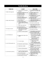
Страница 14: ...r IE running toilet C Eliminate sources of leaks 4 Loss of water pressure A Softener too small for application A Check application requirements and resize water softener as required B Foreign material buildup in water softener B Perform an extended backwash 1 Place unit in manual regeneration 2 When backwash begins unplug the unit from the electrical outlet 3 Allow unit to remain in backwash for 3...

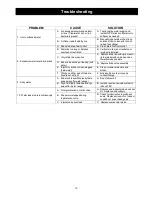
Страница 15: ...ks and as few elbows as possible D Brine valve sticking or leaking soft water D Replace brine valve assembly E Injector or injector screen plugged hard water E Clean or replace injectors and screen F Fittings on either end of the brine line are not air tight F Fully insert brine line into quick connect fittings 9 Salty water A Brine tank is overfilled salty taste goes away after water usage A See ...

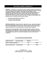
Страница 16: ...function occur contact the dealer that you purchased the product from If you are unable to contact the dealer contact First Sales LLC 260 693 1972 We will require a full description of the problem model number date of purchase and selling dealer s business name and address We assume no warranty liability in connection with this water conditioner other than specified herein This warranty is in lieu...

Отзывы: