First Alert HS-4705-400 Скачать руководство пользователя страница 10

Page  18

Page  19

b

asIc

 o

peratIon

recording

b

asIc

 o

peratIon

recording

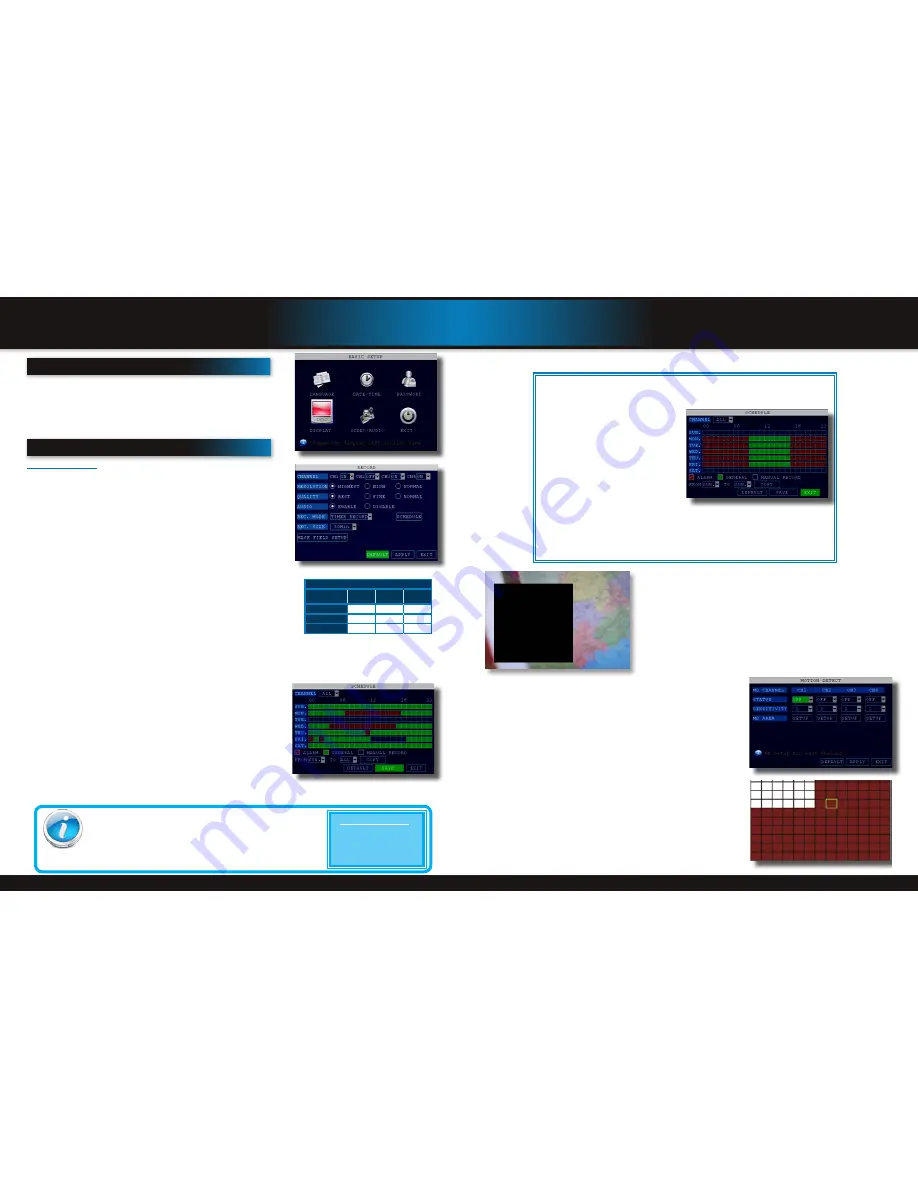
Recording Schedule (TIMER RECORD) Example

Privacy Mask Field

MASK FIELD lets you block a specific portion of a channel you do not want 
recorded or shown on the display screen. This can be useful if you need to 
conceal a sensitive area being captured by the camera. To use the Privacy Mask 
Field:
1.  From the Record menu, click MASK FIELD. The Mask Field menu opens.
2.  Choose a channel you wish to apply the Mask Field.
3.  Select ON from the SWITCH drop-down menu.
4.  Click SETUP. The Mask menu will be replaced by the full-screen camera view   
 

of the desired channel. Using the mouse, click and drag the cursor over the    


area you want to conceal. A single click will produce a small black square.

5.  Right-click anywhere on the screen to return to the Mask Field menu.
6.  Click APPLY. Click OK in the REMARK window. Click EXIT.

Motion Detect Setup

You can configure motion detection for each channel (Camera) connected to the 
DVR. To configure motion detection:

1.  From the Main Menu click ADVANCED. Then click MD (Motion Detect).
2.  Under STATUS, select ON to enable motion detection for the desired chan-

nel.

3.  Under SENSITIVITY, select 1 through 4. The higher the number, the more 

sensitive the motion detection.

4.  Under MD AREA SETUP, click SETUP. The red motion grid appears over the 

selected channel in full screen.

5.  Click the blocks in the grid to enable/disable motion detection. Red=motion 

detection enabled; Clear=motion detection disabled.

6.  Right-click anywhere on the screen to return to the Motion Detection menu.
7.  Click APPLY. Click SURE in the confirmation window.
8.  Click EXIT in all menus until all windows are closed. 

NOTE: You can disable the MD buzzer in the Alarm Setup menu.

When MD is triggered, in the Live View Screen you will see a red

M

in the 

Channel with a MD warning. You may also see a

R

if you set up the channel 

to record when an alarm is triggered.

You want your system to record continuously on all channels from 9 AM to 5 PM Monday to 
Friday. You also want Alarm/Motion recording from 5 PM to 9 AM. You do not want the 
system to record Saturday or Sunday:

1.  Open the Schedule menu.
2.  Under CHANNEL, select ALL.
3.  Click the blue NO RECORD block be-

low the grid. A checkmark will appear 
in the block.

4.  Under SUN, click blocks 00~23. The 

blocks will turn blue.

5.  Under FROM, select SUN. Under TO 

select SAT, and then click COPY.

6.  Click the red ALARM block below the 

grid.

7.  Under MON, click blocks 00~08 and 

blocks 17~23. The blocks will turn red.

8.  Under FROM, select MON. Under 

TO select TUE, and then click COPY. 
Repeat for Wednesday, Thursday, and Friday. Your completed schedule should the 
same as the schedule to the right.

9.  Click SAVE. Click CLOSE in the confirmation window. Click EXIT in all menus until all 

windows are closed.

Recording Schedule

Motion Detect Menu

Motion Detect Grid

b

asIc

 s

etup

Use the BASIC SETUP menu to configure language, date and time settings, 

password setup, along with display, video and audio settings. You can also exit 

the system through this menu. The Basic Setup menu contains the following 

sub-menus: Language, Date/Time, Password, Display, Video/Audio and Exit.

r

ecordIng

RECORD Mode

Configure Recording Options:

You have three recording options: 

Continuous

Schedule

 and 

Motion

. By default, 

the DVR is set to record continuously. Set parameters as follows:
1.  From the Main Menu click RECORD. Under CHANNEL, use the drop-down 

menus and select ON/OFF to enable/disable recording from the selected 
channel. Note: If CHANNEL is set to OFF, then Motion Detect, Alarm and 
Manual Record are also disabled for that channel.

2.  Under RESOLUTION, select Highest, High and Normal.  

NOTE: NTSC: @30fps, PAL: @25fps. Recording capabilities for both NTSC & 
PAL: Channels 1 - 4: D1, HD1, CIF.

3.  Under QUALITY, select Best, Fine or Normal. This relates to bitrate in Kbps.
4.  AUDIO, select ENABLE or DISABLE. If audio recording is enabled, the system 

will record audio from connected audio capable cameras (not included). See 
caution statement on audio recording in 

Video/Audio

 section.

5.  REC. MODE, select POWER UP or TIMER RECORD. If you select POWER UP, 

the system will record continuously (Normal Recording) when the system is 
powered on. If you select TIMER RECORD, you have to set a recording  
schedule on the system.

6.  REC. SIZE (Record Size), select 15MIN, 30MIN, 45MIN, or 60MIN. 

NOTE: Record Size sets the file size for recorded video files on the system. 
Instead of recording data as one large file, the system will divide the data into 
blocks of 15, 30, 45, or 60 minutes. This makes the recorded data easier to search

7.  MASK FIELD lets you block a specific portion of a channel you do not want recorded or shown on the display screen. This 

can be useful if you need to conceal a sensitive area being captured by the camera. See next section for details.

8.  Click APPLY. Click SURE in the REMARK window. Click EXIT.

Recording Schedule (TIMER RECORD)

You can program the DVR to record according to a customized recording 
schedule. The Schedule Grid shows the days of the week and hour blocks 
00~23. You can set Alarm Recording (Red), General Recording (Green), or Manual 
Recording (Blue) to each time block of each day. To set a recording schedule:
1.  Open the Main Menu and click RECORD.
2.  Under REC. MODE, select TIMER RECORD.
3.  Click SCHEDULE. The Schedule menu opens.
4.  Under CHANNEL, select specific channels or select ALL.
5.  Below the grid, click either ALARM (red), GENERAL (Green), or MANUAL 

RECORD (Blue) and then click a time block on the desired day.

6.  Use the FROM/TO drop-down menus to copy the schedule of one day to 

another. For example, if you want your schedule for Monday to be the same 
on Wednesday: under FROM select MON, under TO select WED, and then click COPY.

7.  Click APPLY. Click OK in the REMARK window. Click EXIT.

Record Menu

Recording Schedule

CCTV Resolution

CCTV resolution is measured in vertical and horizontal pixel dimensions and typically 
limited by the capabilities of both the camera and the recorder that you are using for 
your CCTV surveillance installation.  CCTV systems use an analog video signal.  For 
television specifications (which CCTV uses) the highest resolution that can be captured 

and stored is 704 x 480 (NTSC for the United States) and 720 x 576 (PAL for Europe).  This resolution 
is known as D1 resolution.  A high end CCTV recorder is capable of recording at up to D1 resolution.  

CCTV Resolutions

D1: 704 x 480
HD1 (2CIF): 704 x 240
CIF: 352 x 240
QCIF: 176 x 120

Bitrate in Kbps

Image  

Quality

Normal

Fine

Best

Normal (CIF)

384

512

768

High (HD1)

512

768

1024

Highest (D1)

512

768

1024

Basic Setup Menu

Содержание HS-4705-400

Страница 1: ...mobile phone web ready night vision 7 LCD with built in DVR USER S MANUAL Model HS 4705 400 4 Channels 4 Cameras 500GB DVR indoor outdoor 400 TVL cameras advanced video compression H 264 500GB ...

Страница 2: ...tal video recorder with Internet remote surveillance motion detection PTZ and alarm control suitable for applications such as high end residential new or remodel light commercial small business retail small warehouse or small grocery Product features H 264 Compression Virus free Linux O S Real hexaplex operation simultaneous record playback mobile phone live view backup control remote access 500GB...

Страница 3: ...ntain 24 Upgrade Firmware 24 PTZ Setup and Control 25 Step 1 Connect your PTZ Camera to this DVR 25 Step 2 Configure PTZ Communication Settings 25 Step 3 Configure the Operation and Control of your PTZ Camera s 25 Step 4 Configure the CRUISE SETTING of your PTZ Camera 26 7 Remote Access 27 Network Setup for Remote Access 27 DHCP Dynamic Host Configuration Protocol 27 Static IP 27 UPnP Universal Pl...

Страница 4: ...ed by turning the equipment off and on the user is encouraged to try to correct the interference by one or more of the following measures Reorient or relocate the receiving antenna Increase the separation between the equipment and receiver Connect the equipment into an outlet on a circuit different from that of the receiver Consult the dealer or an experienced radio or TV technician for help Notic...

Страница 5: ...irmware upgrades Connect a USB mouse to the right port 6 IR Sensor IR receiver for the remote control 7 LED Indicators Visual indicators for Power Record Alarm Hard Drive HDD and Network Status 8 Main Screen 7 LCD Color Monitor Front Panel 2 1 7 6 5 4 3 8 Back Panel Item Function Description 1 POWER Input DC 12V 3A power connection 2 Network For connecting RJ45 ethernet cable to PC or router 3 Vid...

Страница 6: ...Overview remote control Product Overview mouse and virtual keypad Mouse Operation with this DVR The mouse is the primary input device for navigating system menus NOTE Unless otherwise noted all system functions described in this manual are achieved through mouse input To use a mouse with the system Connect a USB mouse to the USB MOUSE port on back panel of the system NOTE Only the USB 2 0 port on ...

Страница 7: ...ble BNC DC Power 1 per Camera BNC to Security Camera Monitor Not included RJ45 Ethernet to Router and Internet PTZ and Alarm Connections PTZ Cameras not included Follow this diagram to make device connections Note some devices are not included with this kit See What s in the Box for included devices DVR Front Face Connect USB Drive RCA Audio Out to Powered Speakers Not included Smartphone through ...

Страница 8: ...the system 3 HDD Display hard drive status and format the internal hard drive of the system 4 BASIC Open the Basic Setup Menu which lets you set the system language date and time device IDs and passwords and configure display audio and video settings 5 ADVANCE Opens the Advanced Setup Menu which lets you view system info configure alarm PTZ motion detect maintenance mobile and network settings 6 E...

Страница 9: ...vidual scan lines PAL Phase Alternating Line is the predominant video system or standard mostly used overseas In PAL 25 frames are transmitted each second Each frame is made up of 625 individual scan lines Language Date And Time Setting Up Language Date Time Set the system language date and time passwords and configure audio and display options The Basic Setup Menu contains the following sub menus...

Страница 10: ... Mode Configure Recording Options You have three recording options Continuous Schedule and Motion By default the DVR is set to record continuously Set parameters as follows 1 From the Main Menu click RECORD Under CHANNEL use the drop down menus and select ON OFF to enable disable recording from the selected channel Note If CHANNEL is set to OFF then Motion Detect Alarm and Manual Record are also d...

Страница 11: ...for matting the system will restart ATTENTION Formatting the internal HDD erases all video data This step cannot be Undone Hard Drive Format Warning Playback PLAYBACK Mode Playback and Record Search View recorded video on the system through the RECORD SEARCH Menu To begin playback 1 There are two ways to access the VIDEO SEARCH menu Right click anywhere on the screen and select VIDEO SEARCH from t...

Страница 12: ... the alert e mails to go to a different account than the one sending them From NO or NC depending on setup selected to alarm inputs 1 through 4 COM NO NC Example Device Door Sensor Use 5V from Alarm Block GND 5V N A N A GND GND 1NO 1COM 1 4 3 2 ALM IN Alarm Inputs Configuration for devices without voltage Note If Alarm Input Device has its own power supply make sure 1 Voltage rating is between 6V ...

Страница 13: ...k OK This is useful if you want to manually operate the camera without continuously holding or clicking the arrows PTZ Camera Setup NOTE It is recommended for best results to use 120Ω shielded twisted pair cable of a sufficient gauge to meet your application length 18 to 22 gauge is usually sufficient In addition be sure to only install the 120Ω terminating resistor that comes with your PTZ camera...

Страница 14: ...addresses These you will enter into the STATIC IP screen in the NETWORK SETTINGS menu in your DVR See next step Network Setup Windows ipconfig Info Example Pan Tilt Zoom PTZ Setup Continued In the PTZ Senior Control screen you can set or control the following for each PRESET defined 1 SET PRESET Saves any PRESET functions changed with this screen 2 CLEAN PRESET Clears a defined PRESET without goin...

Страница 15: ...tart Run Type CMD and press Enter In the Command Prompt window type ipconfig and press Enter 2 View its WAN settings Write down the Primary or Secondary DNS address for use in the next step DynDNS com Setup Screen WAN Settings Example To configure Static IP settings in the DVR 1 Select STATIC IP from the TYPE drop down box in the NETWORK SETUP Menu 2 Enter your IP Address Subnet mask and Gateway i...

Страница 16: ...if you obtained your domain name from DynDNS com 4 Under DOMAIN NAME enter your DDNS domain name you received from the confirmation email For example if your domain name is adam dyndns com you need to enter adam dyndns com in the text field using the Virtual Keyboard 5 Enter your DDNS user name and password in the respective fields 6 Click APPLY Click OK in the confirmation window 7 Click EXIT The...

Страница 17: ...nge 5 Select Turn User Account Control on or off Note Depending on your version of Vista this screen might be accessible on the bottom of the Select User Account to Change screen under Additional things you can do Go to main user ac count page 6 Uncheck the box next to Use User Account Control UAC to help protect your computer 7 You will need to re start your computer for the change to take effect...

Страница 18: ...sked Are you sure you want to change the setting for this zone 15 Click OK 16 Click Apply 17 Click OK 18 Close Internet Explorer You are now ready to access the DVR using Internet Explorer 8 Using Remote Surveillance With your system connected to your local area network you can now log in to your system using Internet Explorer The software from the DVR will install the first time you access the DV...

Страница 19: ...ording to your PC on ALL channels For more details see RECORDING 5 Select a channel outlined in red and then click the audio bars to increase or decrease listen in volume Click the icon to mute unmute Recording You can record video directly to your PC using the remote surveillance software To record video to your PC from Live viewing click to start stop manual recording to your PC on ALL channels ...

Страница 20: ...corded video data will appear in bold 2 Click the date Recorded video files will populate the File List 3 From the Channel drop down menu select a specific channel or select ALL CHANNEL and then click SEARCH 4 From the Type drop down menu select COMMON normal recording ALARM or ALL TYPE and then click SEARCH 5 Double click the file from the File List to playback the file in the main screen Remote ...

Страница 21: ...ward port 100 as described in the Port Forwarding section of this manual Download Software Step 1 Program Download Copy the installation program Meyesetup CAB from the Installation CD to the My Documents folder on your mobile phone Select Install Path Step 2 Select Install Path Click the program and start to install it just select default path when it ask you to select install path Install Softwar...

Страница 22: ...r the program is finished installing Step 6 Launch Program After installed click the QQeye icon to run the program Mobile Phone setup and control Mobile Phone setup and control Step 6 Main Interface and Controls Channel Select the channel you want to monitor When you select a channel it will connect to DVR automatically Connect Connects and Disconnects to the DVR Settings You will need to enter th...

Страница 23: ...a displays in groups of 8 i e 1 8 9 16 etc depending on how many channels your system can support and how many cameras you have connected Mobile Phone setup and control Step 7 Main Interface and Controls Snapshot default save path is C Data Images Button Definitions Note you must have a PTZ camera s connected for PTZ functions to operate The NextGroup button switches the camera displays in groups ...

Страница 24: ...R Apple iPhone on 3G Networks Your DVR can be configured to be viewed remotely on your iPhone or iPad using the MEye software System requirements iPhone or iPad 2 0 or greater with at least 800KB of free space iTunes is optional 1 Open your iPhone and click App Store 2 Under the search bar type Meye and click search button Download the Mobile Viewing Application for free the file name is Meye 3 Cl...

Страница 25: ... be the same as on the DVR Blackberry Operational Screen Mode Main Screen Video Display Mode You can switch between full screen and regular screen mode Mobile Phone setup and control Mobile Phone setup and control Blackberry OS 5 0 Phones Curve 8900 Bold 9700 Tour 9630 Your DVR can be configured to be viewed remotely using a smartphone running the BlackBerry mobile OS version 5 0 using the MEye so...

Страница 26: ... TO THE DVR OR ITS COMPONENTS AS WELL AS INJURY OR DEATH 2 Remove screws securing the cover of the DVR and remove cover 3 Disconnect the hard drive power and data cables 4 Remove the screws securing the hard drive rails to the chassis See image at right 5 Remove screws securing hard drive rails to hard drive 6 Remove old hard drive and replace with the new one 7 Re install the screws securing the ...

Страница 27: ...ons and cannot be al located to recording resources A frame rate of 420 fps is the maximum that can be allocated Appendix FAQ s Appendix FAQ s FAQ s If your problem is not listed below please call our toll free number for more support Tech Services 800 323 9005 Question Why is the DVR not working after starting Answer Check the power adaptor input Check the on off power line is it well connected C...

Страница 28: ...luding but not limited to loss profits downtime goodwill damage to or replacement of equipment and property and any costs of recovering reprogramming or reproducing any program or data stored in or used with a system containing the product accompanying software BRK does not warrant the software will operate with any other software except that which is indicated BRK cannot be responsible for charac...

Страница 29: ... 2012 BRK Brands Inc a Jarden Corporation Company NYSE JAH 3901 Liberty Street Road Aurora IL 60504 8122 Phone 630 851 7330 Tech Services 800 323 9005 www brkelectronics com M08 0399 002 ...

Отзывы: