8
AP User Guide
February 2009
In order to avoid climbing up and down the pole twice, power up the HotPoint before proceeding
with the installation. The only connection you need is the Ethernet; it provides power as well.
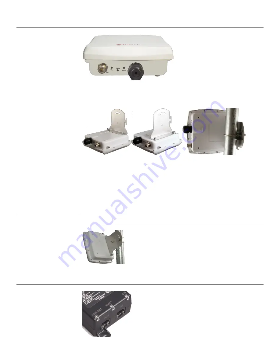
Figure 5. HotPoint Outdoor Unit Connections
Attach the bracket to the back of the HotPoint, using the two slotted holes shown on the right side
of the bracket, as shown in Figure 4. Select two holes on the HotPoint according to the desired
orientation of the pole and the antenna, as shown in Figure 6, left and center.
Figure 6. Attaching the Bracket to the HotPoint
The bracket is attached to the pole using the U-bolt and one or two of the supplied jaw-clamps
(top left in Figure 4). One jaw-clamp is used between the bracket and the pole; the second clamp
may be used on smaller-diameter poles by placing it over the U-bolt before putting the U-bolt
around the pole.
After placing the U-bolt around the pole, place the bracket over the legs of the U-bolt such that
one leg passes through the round hole and the other leg passes through the curved slot. Snug the
bracket slightly with the supplied nuts and lockwashers, but do not tighten until you have aligned
the unit. The result should resemble Figure 6, right.
Aiming the HotPoint
Figure 7 shows how the bracket can be used to tilt the unit. This is especially useful if service
coverage is to be provided near ground level from an AP that is placed high on a pole or near a
building ceiling.
Figure 7. Tilting the Unit
The Firetide HotPoint 4200 requires power. Power is fed via Ethernet. Connect the power-feed unit
to AC power. The ON light should turn green. Plug the cable from the HotPoint into the port marked
OUT. The CONNECT light should turn green. If the FAULT light comes on, contact Firetide.
Figure 8. Power-Feed Unit Connections


