background image

4


Installation 

1.


FirePro generators

 must

 remain disconnected until system is completed and fire control 

panel is no longer in a fault or alarm condition. The FirePro Universal Test Lamp (P/N FP-
08800) can be used to take the panel out of a fault condition. 

2.


Ensure programming of fire control panel is set for extended discharge.  (See FP-08450 or 
FP-08451 Manual) 

3.


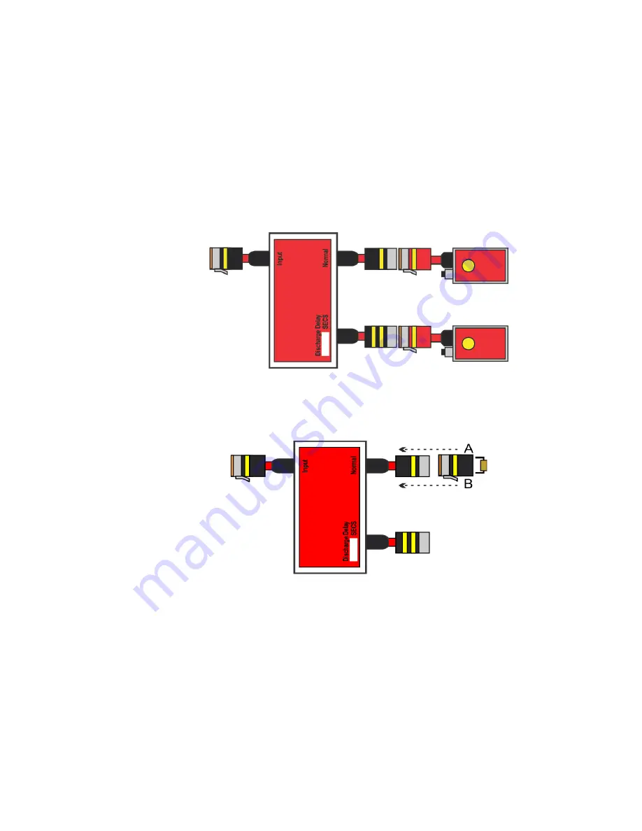
Identify the FirePro generators to be activated in the initial discharge.  The cable to these 

should be connected in series to the “

N

ormal” output on the module

 (marked yellow 1), 

using the FP-08919 Splitter Lead where necessary.  A Universal Test Lamp (P/N FP-08800) 
should be connected at each point where a FirePro generator has been installed. 


4.


If  only  using  the  “Delayed  Discharge”  output,  the  3k3Ω  End

-of-line  resistor  should  be 

terminated into the supplied 3 pin deutsch plug and then connected to the “Normal” output 

on  the  module  (marked  yellow  1).    The  end-of-line  plug  should  then  be  covered  in 
heatshrink, and the heatshrink crimped, to avoid ingress of water into the circuit. 


5.


If using 

multiple modules, the next module should now be connected to the “Discharge 

Delay” output on the first module and step 2 repeated.


6.


Identify the FirePro generators to be activated in the secondary discharge.  The cable to 
these shoul

d be connected in series to the “Discharge Delay” output on the module

 (marked 

yellow 2), using the FP-08919 Splitter Lead where necessary.  A Universal Test Lamp (P/N 
FP-08800) should be connected at each point where a FirePro generator has been installed. 

7.


The settings of the Discharge Delay Module can now be programmed to suit vehicle or site 
specific requirements.  (See 6. Programming) 

Содержание FP-08850

Страница 1: ...ischarge Delay Module 3 3 4 Maximum Number of Discharge Delay Modules that can be used 3 3 5 Mounting 4 3 6 Cabling Requirements 4 3 7 Multiple Discharges Voltage Limitations 4 3 8 Connecting Multiple...

Страница 2: ...mer that can be used to delay the activation of the FirePro generators until suitable This can be set to account for vehicle or site specific conditions for example large areas of leakage time allowan...

Страница 3: ...perating ONLY AFTER DELAY The 3k3 EOL resistor must be in place on the Normal output of a fault will display 3 4 Maximum FirePro units that may be connected 12v DC 2 units per output 24v DC 4 units pe...

Страница 4: ...remain secure Male plugs locking mechanism is orange Female plugs locking mechanism is green 5 Using the heat shrink seal the back of the plug Cables are colour coded for easy identification When inst...

Страница 5: ...dules must not be connected together by the normal output 3 10 Connecting Multiple FirePro Generators If multiple FirePro Generators are being installed on a single output they must be connected using...

Страница 6: ...d Discharge output the 3k3 End of line resistor should be terminated into the supplied 3 pin deutsch plug and then connected to the Normal output on the module marked yellow 1 The end of line plug sho...

Страница 7: ...ds after the FIP has entered an alarm condition Individual programming of modules must not exceed 4 5 minutes the total time power is applied to the activation circuit Mode Delay Timer Switch Mode Del...

Страница 8: ...separate delay value in seconds as follows The delay time is programmed by setting the required switches to the OFF position When multiple switches are used the delay values are added together allowi...

Страница 9: ...nnect the FirePro FP 08800 Universal Test Lamp and reconnect all installed FirePro aerosol generators 8 Servicing and Maintenance Inspection and servicing of the installed fire system should occur in...

Страница 10: ...talled generators exceeds maximum OR FirePro Generators have discharged Check connection of any extension cables Inspect condition of FirePro Generators Check internal battery of FirePro Test lamp For...

Отзывы: