FIREPOWER 160 S SAFETY AND INSTALLATION
Safety and Installation
3-4
3-4
Manual 0-5371
UK Version
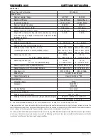
Power Source Part Number
W1003604
Mains Power
Nominal Supply Voltage
AC 110V
AC 230V
Number of Phases
Single Phase
Single Phase
Input Voltage Range
AC 104- 127V
AC 187- 253V
Nominal Supply Frequency
50/60 Hz
50/60 Hz
Effective Input Current (l1eff)
17.8 Amps
14.7 Amps
Maximum Input Current (l1 max)
∆ 35.5 Amps
∆ 23.2 Amps
Single Phase Generator Requirements [Continuous rating
at nominal supply voltage with maximum output for STICK
(SMAW) welding]
5 KVA
6 KVA
Welding Output
Welding Current Range
10 - 125 Amps
10 - 160 Amps
Nominal DC Open Circuit Voltage (OCV)
71V
71V
Welding Output, 104º F (40º C), 10 min.
(Quoted figures refer to STICK (SMAW) output)
125A @ 20%, 25.0V
80A @ 60%, 23.2V
60A @ 100%, 22.4V
160A @ 35%, 26.4V
100A @ 60%, 24.0V
80A @ 100%, 23.2V
Rated Input Current (A)
35.5A
23.2A
for STICK (SMAW) Welding
Io = 125A @ 25.0V
Io = 160A @ 26.4V
Rated Input Current (A)
21.3A
14.4A
for LIFT TIG (GTAW) Welding
Io = 125A @ 15V
Io = 160A @ 16.4V
Rated Output for STICK (SMAW) Welding
25.0V, 125A @ 20%
26.4V, 160A @ 35%
Rated Output for LIFT TIG (GTAW) Welding
15V, 125A @ 50%
16.4V, 160A @ 40%
Duty Cycle (%)
20% @ 125A
35% @ 160A
Welder Type
Inverter Power Source
Output Terminal Type
Heavy Duty Dinse
TM
50
Classification
Protection Class
IP23S
Standards
EN 60974-1
EN50199
Cooling Method
Fan Cooled
Dimensions and Weight
Welding Power Source Mass
7.9 kg (17.4 lb.)
Welding Power Source Dimensions (Height x Width x Depth)
H230mm x W135mm x D393mm
(H 9.0” x W 5.3” x D 15.5” )
∆
The recommended time delay fuse or circuit breaker size is 32 amp for 110V and 32 amp for 230V.
Firepower continuously strives to produce the best product possible and therefore reserves the right to change, improve or revise the
specifications or design of this or any product without prior notice. Such updates or changes do not entitle the buyer of equipment previously
sold or shipped to the corresponding changes, updates, improvements or replacement of such items.
The values specified in the table above are optimal values, your values may differ. Individual equipment may differ from the above specifications
due to in part, but not exclusively, to any one or more of the following; variations or changes in manufactured components, installation
location and conditions and local power grid supply conditions.
.
Содержание TIG 160S
Страница 6: ...This Page Intentionally Blank ...
Страница 15: ...SAFETY INSTRUCTIONS AND WARNINGS FIREPOWER 160 S Manual 0 5371 1 9 Safety Instructions and Warnings Notes ...
Страница 18: ...FIREPOWER 160 S INTRODUCTION Introduction 2 2 Manual 0 5371 Notes ...
Страница 30: ...FIREPOWER 160 S SAFETY AND INSTALLATION Safety and Installation 3 12 Manual 0 5371 Notes ...
Страница 40: ...FIREPOWER 160 S THEORY OF OPERATION Theory of Operation 5 2 Manual 0 5371 Notes ...
Страница 54: ...FIREPOWER 160 S TROUBLESHOOTING Troubleshooting 6 14 Manual 0 5371 Notes ...
Страница 59: ...DISASSEMBLY PROCEDURE FIREPOWER 160 S Manual 0 5371 7 5 Disassembly Procedure 4 Art A 09866 ...
Страница 61: ...DISASSEMBLY PROCEDURE FIREPOWER 160 S Manual 0 5371 7 7 Disassembly Procedure Art A 09868 4 5 Art A 09870 ...
Страница 63: ...DISASSEMBLY PROCEDURE FIREPOWER 160 S Manual 0 5371 7 9 Disassembly Procedure 4 Art A 09873 5 Art A 09876 ...
Страница 66: ...FIREPOWER 160 S DISASSEMBLY PROCEDURE Disassembly Procedur 7 12 Manual 0 5371 Notes ...
Страница 69: ...ASSEMBLY PROCEDURES FIREPOWER 160 S Manual 0 5371 8 3 Assembly Procedures 8 Art A 09883 ...
Страница 74: ...FIREPOWER 160 S ASSEMBLY PROCEDURES Assembly Procedures 8 8 Manual 0 5371 Notes ...
Страница 78: ...FIREPOWER 160 S REPLACEMENT PARTS Replacement Parts 9 4 Manual 0 5371 Notes ...
Страница 80: ...FIREPOWER 160 S ACCESSORIES Accessories 10 2 Manual 0 5371 Notes ...
Страница 83: ......


