background image

6

NFOD42 Gas Fireplace

INSTALLATION

,03257$170(66$*(

6$9(7+(6(

,16758&7,216

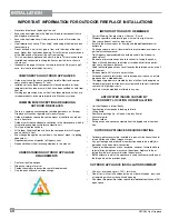
The NFOD42 Gas Fireplace must be installed in 
accordance with these instructions. Carefully read 
all the instructions in this manual first. Consult the 
"authority having jurisdiction" to determine the need 
for a permit prior to starting the installation. It is the 
responsibility of the installer to ensure this fireplace 
is  installed  in  compliance  with  manufacturers 
instructions and all applicable codes.

%()25(<2867$57

Safe  installation  and  operation  of  this  appliance 
requires common sense, however, we are required 
by  the  Canadian  Safety  Standards  and  ANSI 
Standards to make you aware of the following:

*(1(5$/6$)(7<

,1)250$7,21

The  installation  must  conform  with  local 
codes or, in the absence of local codes, with 

%#0%5#$

, Natural Gas and Propane 

Installation Code or 

%#0%5#$

, Propane 

installation code the Natural Gas Fuel Code, 

#05+<0(2#

.

  The  appliance  when  installed,  must  be 

electrically grounded in accordance with local 
codes, or in the absence of local codes with the 
Canadian  Electrical  Code  CSA  C22.1or  with 
the National Electrical Code, ANSI/NFPA 70.

  See  general  construction  and  assembly 

instructions. The appliance should be enclosed.

  Inspect  the  burner  before  each  use  of  the 

appliance  for  blockage  and  any  signs  of 
deterioration.   

CHILDREN  AND  ADULTS  SHOULD 
BE  ALERTED  TO  THE  HAZARDS  OF 
HIGH  SURFACE  TEMPERATURES, 
ESPECIALLY THE FIREPLACE GLASS 
AND FACEPLATE, AND SHOULD STAY 
AWAY TO AVOID BURNS OR CLOTHING 
IGNITION.  

THIS  APPLIANCE  SHALL  BE  USED 
ONLY  OUTDOORS  IN  A WELL-VENTI-
LATED  SPACE  AND  SHALL  NOT  BE 
USED IN A BUILDING, GARAGE OR ANY 
OTHER ENCLOSED AREA.

INSTALLATION AND REPAIR SHOULD 
BE  DONE  BY  AN  AUTHORIZED 
SERVICE  PERSON.  THE  APPLIANCE 
SHOULD  BE  INSPECTED  BEFORE 
USE AND AT LEAST ANNUALLY BY A 
PROFESSIONAL  SERVICE  PERSON. 
MORE  FREQUENT  CLEANING  MAY 
BE  REQUIRED  DUE  TO  EXCESSIVE 
LINT  FROM  CARPETING,  BEDDING 
MATERIAL, ETC. IT IS IMPERATIVE THAT 
CONTROL COMPARTMENTS, BURNERS 
AND CIRCULATING AIR PASSAGEWAYS 
OF THE APPLIANCE BE KEPT CLEAN.

ANY GUARD OR OTHER PROTECTIVE 
DEVICE  REMOVED  FOR  SERVICING 
THE APPLIANCE MUST BE REPLACED 
PRIOR TO OPERATING THE APPLIANCE

WARNING: FAILURE TO INSTALL THIS 
APPLIANCE  CORRECTLY  WILL  VOID 
YOUR WARRANTY AND MAY CAUSE A 
SERIOUS FIRE.

CLOTHING  OR  OTHER  FLAMMABLE 
MATERIAL SHOULD NOT BE PLACED 
ON OR NEAR THE APPLIANCE.


DO  NOT  USE  THIS  APPLIANCE  IF 
ANY PART HAS BEEN UNDER WATER. 
IMMEDIATELY  CALL  A  QUALIFIED 
SERVICE  TECHNICIAN  TO  INSPECT 
THE  APPLIANCE  AND  TO  REPLACE 
ANY PART OF THE CONTROL SYSTEM 
AND ANY GAS CONTROL WHICH HAS 
BEEN UNDER WATER.

YOUNG CHILDREN SHOULD BE CARE-
FULLY  SUPERVISED WHEN THEY ARE 
IN  THE  SAME  AREA  AS  THE  APPLI-
ANCE.  TODDLERS, YOUNG CHILDREN 
AND OTHERS MAY BE SUSCEPTIBLE 
TO ACCIDENTAL CONTACT BURNS.  A 
PHYSICAL BARRIERS IS RECOMMEND-
ED IF THERE ARE AT RISK INDIVIDUAL 
IN THE HOUSE.  TO RESTRICT ACCESS 
TO A FIREPLACE OR STOVE, INSTALL 
AN  ADJUSTABLE  SAFETY  GATE  TO 
KEEP TODDLERS, YOUNG  CHILDREN 
AND OTHER AT RISK INDIVIDUALS OUT 
OF THE ROOM AND AWAY FROM HOT 
SURFACES. 

  To prevent injury, do not allow anyone who is 

unfamiliar with the operation to use the fireplace.

  Wear gloves and safety glasses for protection 

while doing required maintenance.

7)

  Maximum gas inlet pressure = 1/2 psig.

  Under no circumstances should this appliance 

be modified. Parts that have to be removed for 
servicing should be replaced prior to operating 
this appliance.

  Installation and any repairs to this appliance 

should be done by a qualified service person. 
A professional service person should be called 
to  inspect  this  appliance  annually.  Make  it  a 
practice  to  have  all  of  your  gas  appliances 
checked annually.

 Under no circumstances should any solid fuels 

(wood, paper, cardboard, coal, etc.) be used in 
this appliance.

11)

 The appliance and its individual shutoff valve 

must  be  disconnected  from  the  gas  supply 
piping system during any pressure testing of 
that system at test pressures in excess of 1/2 
psi (3.5kPa).

The appliance must be isolated from the gas 
supply piping system by closing its individual 
manual shutoff valve during any pressure testing 
of the gas supply piping system at test pressures 
equal to or less than 1/2 psi (3.5 kPa).

 The  appliance  area  must  be  kept  clear  and 

free of combustible materials, (gases and other 
flammable vapours and liquids).


,WLVKLJKO\UHFRPPHQGHGWRSURWHFWWKH
LQWHULRUIURPPRLVWXUHUDLQVQRZ&RYHU
WKHHQFORVXUHRSHQLQJZKHQQRWLQXVH7KLV
¿UHSODFHLVRQO\IRUXVHZLWKWKHW\SHRIJDV
LQGLFDWHGRQWKHUDWLQJSODWH7KLV¿UHSODFH
LVQRWFRQYHUWLEOHIRUXVHZLWKRWKHUJDVHV
XQOHVVDFHUWL¿HGNLWLVXVHG

  Cover

PXVW

be removed when burner is in

        operation.

14)

 When not using appliance for extended periods 

of time - turn off gas supply.

Emissions from burning  wood or gas could 
contain  chemicals  known  to  the  State  of 
California to  cause cancer, birth defects or 
other reproductive harm.

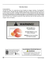
Содержание NFOD42 Series

Страница 1: ...HU IURP D QHLJKERXU V SKRQH ROORZ WKH JDV VXSSOLHU V LQVWUXFWLRQV I RX FDQQRW UHDFK RXU JDV VXSSOLHU FDOO WKH UH GHSDUWPHQW 919 001c 02 25 13 2ZQHUV QVWDOODWLRQ 0DQXDO Tested by QVWDOOHU 3OHDVH FRPSOHWH WKH GHWDLOV RQ WKH EDFN FRYHU DQG OHDYH WKLV PDQXDO ZLWK WKH KRPHRZQHU RPHRZQHU 3OHDVH NHHS WKHVH LQVWUXFWLRQV IRU IXWXUH UHIHUHQFH MODELS NFOD42 N NFOD42 P Night Fire Outdoor 42 Gas Fireplace WARN...

Страница 2: ...mth and charm of a fire at the flick of a switch The Night Fire NFOD42 Outdoor fireplace has been approved by Warnock Hersey Intertek for both safety and efficiency As it also bears our own mark it promises to provide you with economy comfort and security for many trouble free years to follow Please take a moment now to acquaint yourself with these instructions and the many features of your firege...

Страница 3: ...DWLRQ GMXVWPHQW 8QLW VVHPEO 3ULRU WR QVWDOODWLRQ 6WDQGRII VVHPEO 1DLOLQJ 6WULSV UDLQ QVWDOODWLRQ 5HFRPPHQGHG DOO VZLWFK LQVWDOODWLRQ LULQJ LDJUDP QQHU SDQHO LQVWDOODWLRQ LUHJODVV JDUGHQ VWRQH LQVWDOODWLRQ 3HEEOH LQVWDOODWLRQ 2SWLRQDO 7ZLJ 6HW QVWDOODWLRQ HDW GHÀHFWRU LQVWDOODWLRQ DFHSODWH LQVWDOODWLRQ ODVV ZLQG VKLHOG LQVWDOODWLRQ HDWKHU FRYHU LQVWDOODWLRQ UHPRYDO 23 5 7 1 16758 7 216 2SHUDWLQJ QV...

Страница 4: ... Pression à la tubulure d chappement lev e Grandeur de l injecteur D bit maximum selon l altitude Pression d allimentation maximum Calorifique é é é é 14 WC C E 3 49 kPa 11 WC C E 2 74 kPa WC C E 43 500 Btu h 12 74 kW 10 2 49kPa 47 DMS 0 4500 ft pi 0 1372m Minimum supply pressure Manifold pressure high Orifice size Maximum input Altitude Maximum supply pressure D E F A B C Side Walls A 11 279mm B ...

Страница 5: ...place 0 16 216 81 7 0 16 216 41 11 16 1059mm 35 1 4 895mm 23 5 16 592mm 6 5 16 160mm 16 1 8 410mm 13 3 4 349mm 5 8 16mm 17 432mm 12 3 4 324mm 32 7 16 824mm 39 1003mm 15 9 16 395mm 10 254mm 43 11 16 1110mm 37 13 16 960mm ...

Страница 6: ...THE APPLIANCE DO NOT USE THIS APPLIANCE IF ANY PART HAS BEEN UNDER WATER IMMEDIATELY CALL A QUALIFIED SERVICE TECHNICIAN TO INSPECT THE APPLIANCE AND TO REPLACE ANY PART OFTHE CONTROL SYSTEM AND ANY GAS CONTROL WHICH HAS BEEN UNDER WATER YOUNG CHILDREN SHOULD BE CARE FULLY SUPERVISED WHENTHEY ARE IN THE SAME AREA AS THE APPLI ANCE TODDLERS YOUNG CHILDREN AND OTHERS MAY BE SUSCEPTIBLE TO ACCIDENTAL...

Страница 7: ...to Combustibles Refer to Clearances section c Mantel Clearances Refer to Combustible Mantel Clearances section d Framing Finishing Requirements Refer to Framing Finishing section Top Facing Support and Side Nailing Strips Refer to Unit Assembly Prior to Installation Section 1RWH Must be done before installing unit into place Drain Installation QVWDOO 21 2 VZLWFK HQVXUH LW LV LQ WKH 2 SRVLWLRQ Make...

Страница 8: ...e totally open plus one of remaining walls must have a fixed opening All outdoor fireplaces fire tables require total natural ventilation of 50 open space Correct Working Gas pressure is critical on E units Wherever possible avoid locating on a flat wall in a tight corner Floor space doesn t count as open area Install to the manual specs for framing and do not insulate unit or enclosure Framing en...

Страница 9: ... FOHDUDQFHV OLVWHG EHORZ DUH 0LQLPXP GLVWDQFHV XQOHVV RWKHUZLVH VWDWHG PDMRU FDXVH RI UHV LV IDLOXUH WR PDLQWDLQ UHTXLUHG FOHDUDQFHV DLU VSDFH WR FRPEXVWLEOH PDWHULDOV W LV RI WKH JUHDWHVW LPSRUWDQFH WKDW WKLV UHSODFH EH LQVWDOOHG RQO LQ DFFRUGDQFH ZLWK WKHVH LQVWUXFWLRQV F E D A C B NFOD42 Clearance Requirements OHDUDQFH LPHQVLRQ 0HDVXUHG URP 6LGHZDOO 11 203mm Side of Fireplace Opening HLOLQJ 36 ...

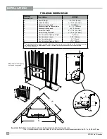
Страница 10: ...g Wall Width 54 3 16 1376mm H Gas Connection Opening Height 2 51mm I Gas Connection Height 3 7 8 98mm J Gas Connection Inset 3 4 73mm K Gas Connection Opening Width 3 7 8 98mm Framing depth measurement is noted with the nailing strips set as far forward on the firebox as possible The nailing strips can be adjusted back up to 1 to allow for varying thicknesses in non combustible material wall finis...

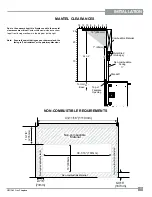
Страница 11: ... XVHG RQ WKH PDQWHO DQG WKH IDFLQJ LV KHDW UHVLVWDQW RU WKH SDLQW PD GLVFRORXU Combustible Material 2 0 12 6 4 8 10 12 305mm Standoff Metal Stud On Edge 0 14 Non combustible Facing To Unit Base 1 25mm 26 1 2 18 23 10 20 26 Top of Fireplace Opening 11 0 17 5 1 6 121 20 867 5 48 5 0 176 2 7 8 3mm 6 9 16 167mm 10 7 8 276mm 16 406mm 38 1 16 767mm Non combustible Material Non combustible Material Non c...

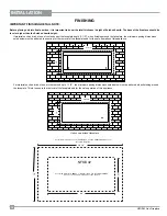
Страница 12: ...H DGKHUHG WR HQVXULQJ IRU WKH UHPRYDO RI WKH IDFHSODWH DQG IRU WKH VDIH RSHUDWLRQ RI WKLV DSSOLDQFH RU PDWHULDO VXFK DV EULFN VWRQH HWF WKDW H WHQG XS WR WKH PLQLPXP RSHQLQJ GLPHQVLRQV QRWHG EHORZ PXVW EH DGKHUHG ZKHQ QLVKLQJ DURXQG WKH IDFHSODWH 7KLV LV WR HQVXUH WKH UHPRYDO RI WKH IDFHSODWH DQG IRU WKH VDIH RSHUDWLRQ RI WKLV DSSOLDQFH For facing material is over 1 25mm thick use the outer cut ou...

Страница 13: ... WKH DHUDWLRQ FRQWUROV LV 127 FRYHUHG XQGHU ZDUUDQW 9 7 21 7KLV XQLW LV DSSURYHG IRU DOWLWXGH WR IW 1 0 6 1 167 7 21 6LQFH VRPH PXQLFLSDOLWLHV KDYH DGGLWLRQDO ORFDO FRGHV LW LV DOZD V EHVW WR FRQVXOW ZLWK RXU ORFDO DXWKRULWLHV DQG WKH 1 LQVWDOODWLRQ FRGH RU 86 LQVWDOODWLRQV IROORZ ORFDO FRGHV DQG RU WKH FXUUHQW 1DWLRQDO XHO DV RGH 16 KHQ XVLQJ FRSSHU RU ÀH FRQQHFWRUV XVH RQO DSSURYHG WWLQJV OZD V ...

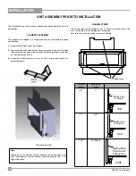
Страница 14: ...ttached Remove the standoffs from the fireplace Take each standoff and bend into the correct shape Bend up at the bend lines until the screw holes in the standoff and the pre punched screw holes on the fireplace top line up Attach the standoff securely to the unit with 2 screws per standoff on opposite corners 5VCPFQHHU KPUVCNNGF 0CKNKPI 5VTKRU 1RWH HSHQGLQJ RQ WKH PDWHULDO XVHG IRU QLVKLQJ WKH QD...

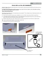
Страница 15: ...to remove the rear access panel from the back of the unit this will allow access to the drain hole at the base of the unit 2 On the exposed drain hole see location below install a PVC 3 4 threaded coupling reducer going from the top of the pan down through the hole Apply a silicone based sealant around the base and threads before installation 3 Holding the reducer coupling with a wrench thread a 9...

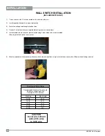
Страница 16: ...s 5 Install weather resistance cover plate to switch using 2 inner holes with screws provided Ensure gasket and spacer are in place 6 Mount completed switch assembly with cover plate to the electrical box using 2 outer holes on cover plate Shown without facing material Thermostat Wire Table Recommended Maximum Lead Length Two Wire When Using Wall Thermostat CP 2 System Wire Size Max Length 14 GA 5...

Страница 17: ...V 127 EDWWHULHV PXVW EH LQVWDOOHG LQ WKH EDWWHU SDFN WR RSHUDWH WKH EXUQHU VZLWFK 5HPRYH WKH SURWHFWLYH FRDWLQJ IURP WKH IROORZLQJ FRPSRQHQWV EHIRUH SURFHHGLQJ DUHIXOO IROORZ VWDLQOHVV KDQGOLQJ LQVWUXFWLRQV RQ IROORZLQJ SDJH 0 886 001 Proflame Valve Standard Main On Off Switch or Optional Wall Switch SureFire Switch 880 Proflame 880 Standard Wall Switch ...

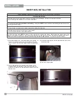
Страница 18: ... a defect All hand and finger marks MUST be cleaned off with a soft cloth and a stainless steel cleaner Most stainless steel cleaners leave a film residue on the surface of the panels Use an ammonia based cleaner ie glass cleaner to remove this film before applying heat to the unit Failure to do this will result in burn stains on panels which you will be unable to remove Not protected by product w...

Страница 19: ...QRW RYHUODS WRR PXFK DV WKLV ZLOO HIIHFW WKH ÀDPH SDWWHUQ 03257 17 127 2QO WKH VXSSOLHG DSSURYHG REDOW ODVV HUDPLF 6SD 6WRQHV RU DUGHQ 6WRQHV DUH WR EH XVHG ZLWK WKHVH UHSODFHV 8VH RI DQ RWKHU W SH RI UHJODVV RU VWRQHV FDQ DOWHU WKH XQLW V SHUIRUPDQFH DQ GDPDJH FDXVHG E WKH XVH RI DQ XQDSSURYHG JODVV RU VWRQHV ZLOO QRW EH FRYHUHG XQGHU ZDUUDQW KHQ XVLQJ HUDPLF RU DUGHQ 6WRQHV 2 127 FRYHU EXUQHU SR...

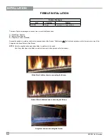
Страница 20: ...UHJODVV FRORUV DYDLODEOH 6SUHDG WKH SHEEOHV FU VWDOV HYHQO RQ WKH H SRVHG EDVH RI WKH UHER 3HEEOHV DUH 127 WR EH SODFHG DQ ZKHUH RQ WKH EXUQHU RU RYHU WRS RI WKH LUHJODVV RU RSWLRQDO HUDPLF 6SD 6WRQHV 127 2QO WKH VXSSOLHG DQG DSSURYHG SHEEOHV FU VWDOV DUH WR EH XVHG 8VH RI DQ RWKHU W SH RI SHEEOHV RU PDWHULDO FDQ FUHDWH D GDQJHU DQG ZLOO YRLG ZDUUDQW LUHJODVV VKRZQ VXUURXQGLQJ WKH XUQHU LUHER 3DFN...

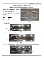
Страница 21: ...oper positioning of the logs may create carbon build up and can alter the unit s performance which is not covered under warranty Log kit 326 930 contains the following pieces Part Description A x 1 Log B x 1 Log C x 1 Log D x 1 Log E x 1 Log Diagram 2 Diagram 1 F E D C B A A C 1 Install logs A and C on the burner as shown below Orient the logs in the same way and in a similar location on the left ...

Страница 22: ...D across log E in the same way and in a similar position as depicted in Diagram 5 log D will rest up against the back panel 5 Install log F on the right side of the burner as shown below Orient log F in the same way and in a similar position as depicted in Diagram 6 Diagram 5 Diagram 6 Final Install D E F ...

Страница 23: ...23 NFOD42 Gas Fireplace INSTALLATION 7 725 167 7 21 1 Install the heat deflector to the top inside of the firebox with 4 screws as shown below GCV GƀGEVQT GCV GƀGEVQT PUVCNNGF ...

Страница 24: ... the C shaped openings on the left and right sides of the unit There are 3 slots on each tab so the faceplate to accommodate different finishing materials 2 Install logo onto faceplate 4 To remove reverse steps 3 For installations where thicker finishing material is used the optional trim piece may be installed to fill the gap Install the trim between the bottom access panel and the faceplate as s...

Страница 25: ... The soft fabric cover is made of weather resistant material to protect the unit from the elements Starting from one corner slide the cover over the corner then stretch the cover until it is fitted over all four corners CAUTION Never start the unit with the cover on Let the unit cool before installing the cover Turn off gas supply to unit before installing cover 66 1 6 167 7 21 QVVQO EEGUU RCPGN 9...

Страница 26: ...the Outdoor fireplace Overall dimensions 60 W x 20 D x 52 1 2 H Non combustible finishing board not supplied with kit Board may be purchased at your local hardware building supply store 326 900 CONTENTS Top Bottom A x 2 Vertical Supports Tall B x 8 Vertical Supports Short C x 6 Base D x 1 Header E x 1 Corner Brace F x 2 Wafer Screws 80 Tools Required 1 power drill 2 phillips bit 1 hand 2 screwdriv...

Страница 27: ...with 2 screws 1 on each side A can be placed into position as shown below Ensure all tabs on the A are bent to 90 and oriented to each B as shown in step 2 5 Line up top A screw holes with B screw holes and secure with B to A with 2 wafer screws 1 on each side 8 in total Note Securing inner B pieces to top A will add rigidity making it easier to lineup and install outer B pieces Important B tall v...

Страница 28: ...Position 4 C pieces with the flat side back to back with the flat side of each inner Part B as shown below Secure each C to bottom A with 3 wafer screws one on each side and one at top as shown below 9 Position remaining 2 C pieces offset from center rib as shown below 10 Position D on top of C pieces line up screw holes and secure D to C with 12 wafer screws 11 Measure 44 11 16 from floor bottom ...

Страница 29: ...corner brace with B A and secure with 4 wafer screws as shown below 15 Repeat step 14 for opposite corner as shown below 16 Final assembly Note Confirm assembly is level and square before proceeding with further materials 13 On the back side of the frame Install both F pieces corner brace on opposite corners Important F parts must be installed opposite from one another for rigidity as shown below ...

Страница 30: ... apart The openings need to be a total area of 1 inð lb 14 2 cmð kg of fuel storage capacity 5 Max 5 Max 2 Min 1 Max Bottom opening must provide a minimum of 1 2 square inches 3 23 cm for each pound of pro pane LP contained in the tank see example be low Every opening must have minimum dimensions to allow entrance of a 1 8 3 2mm diameter rod Ventilation openings in side walls must not communi cate...

Страница 31: ...QRUPDO DQG ZLOO GLVDSSHDU LQ D IHZ PLQXWHV DV WKH JODVV KHDWV XS 23 5 7 1 16758 7 216 5HDG DQG XQGHUVWDQG WKHVH LQVWUXFWLRQV EHIRUH RSHUDWLQJ WKLV DSSOLDQFH KHFN WR VHH WKDW DOO ZLULQJ LV FRUUHFW DQG HQFORVHG WR SUHYHQW SRVVLEOH VKRFN KHFN WR HQVXUH WKHUH DUH QR JDV OHDNV QVXUH WKDW WKH VWDLQOHVV SDQHOV DUH LQVWDOOHG 9HULI ORJ SODFHPHQW I WKH SLORW FDQQRW EH VHHQ ZKHQ OLJKWLQJ WKH XQLW WKH ORJV KD...

Страница 32: ... informations supplé mentaires consulter un installateur qualifié une agence de service ou fournisseur de gaz 918 892a n Grey except ted as being e any wider than cut limited clearance 2 4 16 9 d draft for approval ed size of decal lly lights the pilot Be sure to smell next to floor uilding hegassupplier sinstructions iquement la veilleuse il pour déceler une odeur s que l air et peuvent es se tro...

Страница 33: ...it Failure to do this will result in burn stains on panels which you will be unable to remove The heater is finished in a heat resistant paint and should only be refinished with heat resistant paint firegearOutdoors uses StoveBright Paint Metal lic Black 6309 Make a periodic check of burner for proper position and condition Visually check the flame of the burner periodically making sure the flames...

Страница 34: ...nd panel clip on the right side Remove the right side panel once the clip has been removed 11 Remove left and right screws from the burner legs 9 Remove the front access panel by lifting up and out 10 Remove the burner tray by lifting up and out 7 Remove the screw and panel clip on the left side Remove the left side panel once the clip has been removed 8 Remove the back panel once the 2 side panel...

Страница 35: ...urner Control to the firebox 14 Remove the DFBC from the unit see instructions in manual 15 Remove 6 screws an lift out valve tray 16 Replace with new valve tray and reverse steps Inspect gasket condition replace if necessary Slide the burner to the right and lift up and out of the firebox ...

Страница 36: ...HSODFH EXUQHU FRQWURO ER 6HH LDJUDP EHORZ Disconnect the Black sparker wire with black spade connector from CN3 See Diagram 2 below Disconnect the white and green On Off switch wires See Diagram 3 below Disconnect the yellow ground wire with green diagonal stripe for pilot CN2 See Diagram 4 below Disconnect the three valve wires yellow wire with green stripe See Diagram 5 below LDJUDP LDJUDP LDJUD...

Страница 37: ...ctor 5 904 777 Orifice 29 NG 904 434 Orifice 47 LP 6 326 574 P Valve Assembly NG 326 576 P Valve Assembly LP 7 326 007 P Front access panel 8 326 048 Burner Tray Cover 326 054 Pilot Hood 326 036 Top nailing strip 326 037 F Side nailing strip 326 074 Weather Cover 910 363 Wall Switch 919 001 Manual 1 2 7 5 6 8 ...

Страница 38: ...LSWLRQ 9 326 525 Burner Assembly NG 326 525 Burner Assembly LP 10 911 024 Valve NG SIT 880 911 025 Valve LP SIT 880 12 911 006 Pilot Assembly NG 911 007 Pilot Assembly LP Flame Sensor Igniter 3DUW HVFULSWLRQ 904 777 Orifice 29 NG 904 434 Orifice 47 LP 326 930 Twig Set ...

Страница 39: ...39 NFOD42 Gas Fireplace PARTS LIST 6625 6 3DUW HVFULSWLRQ 14 940 368 P Glass windshield 15 326 552 Faceplate Brushed Stainless 946 676 Copper Fireglass 946 695 Garden Stones 15 14 13 ...

Страница 40: ...40 NFOD42 Gas Fireplace NOTES ...

Страница 41: ...41 NFOD42 Gas Fireplace NOTES ...

Страница 42: ...42 NFOD42 Gas Fireplace NOTES ...

Страница 43: ...arried out on your firegear Outdoors product firegear Outdoors will not be liable for results or costs of workmanship from unauthorized service persons or dealers At all times firegear Outdoors reserves the right to inspect product in the field which is claimed to be defective All claims must be submitted to firegear Outdoors by authorized selling dealers It is essential that all submitted claims ...

Страница 44: ...BBBBBBBBBBBBBBBBBBBBBBBBBBBBBBBBBBBBBBBBBBBBBB DWH QVWDOOHG BBBBBBBBBBBBBBBBBBBBBBBBBBBBBBBBBBBBBBBBBBBBBBBBBBBBBB 6HULDO 1R BBBBBBBBBBBBBBBBBBBBBBBBBBBBBBBBBBBBBBBBBBBBBBBBBBBBBBBBBB UHJHDU 2XWGRRUV UHSODFHV DUH GHVLJQHG ZLWK UHOL DELOLW DQG VLPSOLFLW LQ PLQG Q DGGLWLRQ RXU LQWHU QDO 4XDOLW VVXUDQFH 7HDP FDUHIXOO LQVSHFWV HDFK XQLW WKRURXJKO EHIRUH LW OHDYHV RXU GRRU UHJHDU 2XWGRRUV LV SOHDVHG WR...

Отзывы: