EQUIPMENT:
FIRE
CLASS
PRECEPT EN
WRITTEN BY: RKP
PUBLICATION:
FIRECLASS PREC EN OUTPUT EXP MOD INST
CHECKED BY: AP
ISSUE No. & DATE:
0 02/03/12
PAGE 8 of 21
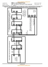
6.2.3 Interconnections between Fire Alarm Panel and Output Modules
The standard output expansion panel combinations are listed below [see Table 2] along with their respective
requirements for interconnection for the 3 types of O/P modules.
Table 2
– Fire Panel/Output Module Interconnection Installation Work
FIRE
CLASS
Precept EN Panel
Expansion Panel
Internal Connections
Schematic
Internal
Cable
Main Panel
Expansion Panel
8-zone & 16-zone
without Output
board
Exp 4 [or Exp5]
no power supply.
Data
Ribbon
Motherboard
[C1627]
connector J17.
Connector J2 on O/P module 1
[left hand most module]
Aux DC
power
cable
Motherboard
[C1627] power
out connector
J24
“Power in” connector on the first
C1633/C1635 module [from the
left hand side of the expansion
panel].
J4 on the C1633/J3 on the
C1635.
32-zone without
Output board
Exp 4 [or Exp5]
no power supply.
Data
Ribbon
Motherboard
[C1627]
connector J17.
Connector J2 on O/P module 1
[left hand most module]
Aux DC
power
cable
Motherboard
[C1627] power
out connector
J24
“Power in” connector on the first
C1633/C1635 module [from the
left hand side of the expansion
panel].
J4 on the C1633/J3 on the
C1635.
8-zone, 16-zone &
32-zone without
Output board
Exp 4 [or Exp5]
with C1652 power
supply.
Data
Ribbon
Motherboard
[C1627]
connector J17.
Connector J2 on O/P module 1
[left hand most module]
Aux DC
power
cable
Factory fitted.
From:
C1652 power supply board 28V,
0V and fault signals from J1.
To:
“Power in” connector on the first
C1633/C1635 module [from the
left hand side of the expansion
panel].
J4 on the C1633/J3 on the
C1635.
8-zone with 1 O/P
module
Exp 4 [or Exp5]
no power supply.
Data
Ribbon
Data out
connector on the
O/P module.
J6 on C1633
and C1635
Connector J2 on O/P module 1
[left hand most module]
[showing 2
x O/P
modules]
Aux DC
power
cable
“Power out”
connector on the
C1633/C1635
module.
J3 on the
C1633/J5 on the
C1635.
“Power in” connector on the first
C1633/C1635 module [from the
left hand side of the expansion
panel].
J4 on the C1633/J3 on the
C1635.


