background image

REV. 01 2016


22 / 28 


7.12      CHECK BEFORE START-UP 


During  this  procedure,  observe  all  operating  components  and  check  for  proper 
installation and adjustment.  
DO  NOT  attempt  to  raise  vehicle  until  a  thorough  operation  check  has  been 
completed. 

 
7.12.1  GENERAL CHECKS 


Make sure all pins and bolts to insure proper mounting. 


Make sure the chain for proper installation.  


Make sure the electrical system feeding voltage is equal to that  specified in the nameplate on 
the  motor,  the  electric  system  connection  in  conformity  of  the  electric  plan  shown  as  the 
electric diagram (fig. 6) and for proper grounding. 


Make sure the lift is connected to the ground. 


Particularly, below checks must be followed:  


7.12.2


MECHANICAL SAFETIES FOR PROPER INSTALLATION 


Check to make sure that safeties will properly engage by pushing the locking button and can be 
released properly but pushing the lowering button. 


When raising the carriages, listen to the safety hook fall into the safety rack. If not, check the 
cause if necessary. 


7.12.3


HYDRAULIC SYSTEM FOR PROPER OPERATION 


Proper oil level in the tank, refill if needed. 


Raise the carriage to the full height and keep the motor running for 5 seconds. 


Check  all  hoses  connections  to  make  sure  no  leakage.  Tighten  the  connections  or  reseal  if 
necessary. 


Check the carriage for reaching its maximum height. 


Repeat the air bleeding of cylinders if necessary.  


7.12.4


LIMIT SWITCH FOR PROPER OPERATION 


Check to make sure the top limit switch for proper operation. Verify that the power unit stops 
working when the carriages reaches the maximum height. 


Check to make sure the safety height limit switch for proper operation. Verify the power unit 
stops working when the carriage is lowered at about 200mm high. 


7.13    ANCHORING COLUMNS 


If  the  lift  is  chosen  to  be  anchored  to  floor,  the  concrete  slab  should  have  the 
compression  strength  of  at  least  3000  PSI  and  the  minimum  thickness  160mm 
with an extension of at least 1.5m from anchoring point. 
The anchor bolts can be ordered from the manufacturer.  


Using the base plate as guide, drill each hole in the concrete approximately 160mm deep with 

the rotary hammer drill D.20. To assure full holding power, do not ream the hole or allow drill 
to wobble. 

Содержание GM - EA700E PRO

Страница 1: ...REV 01 2016 1 28 USE AND MAINTENANCE MANUAL ELECTRO HYDRAULIC MOBILE SINGLE POST LIFT GM EA700E PRO ...

Страница 2: ...s which need proper care Indicates prohibition Indicates a possibility of danger for the operators Indicates the direction of access for motor vehicles to the lift BOLD TYPE Important information WARNING before operating the lift and carrying out any adjustment read carefully chapter 7 installation where all proper operations for a better functioning of the lift are shown ...

Страница 3: ...1 GENERAL INFORMATION 4 2 PRODUCT IDENTIFICATION 6 3 PACKING TRANSPORT AND STORAGE 7 4 PRODUCT DESCRIPTION 8 5 TECHNICAL SPECIFICATION 9 6 SAFETY 16 7 INSTALLATION 18 8 OPERATION AND USE 24 9 MAINTENANCE 27 10 TROUBLESHOOTING 28 ...

Страница 4: ...ed to carry out lifting transport assembling installation adjustment calibration settings extraordinary maintenance repairs overhauling and dismantling of the lift THE MANUFACTURER IS NOT RESPONSIBLE FOR POSSIBLE DAMAGE TO PEOPLE VEHICLES OR OBJECTS IF SAID OPERATIONS ARE CARRIED OUT BY UNAUTHORIZED PERSONNEL OR THE LIFT IS IMPROPERLY USED Any use of the machine made by operators who are not famil...

Страница 5: ...rking life is over and it can no longer be used it must be made inoperative by removing any connection to power sources These units are considered as special waste material and should be broken down into uniform parts and disposed of in compliance with current laws and regulations If the packing are not polluting or non biodegradable deliver them to appropriate handling station DECLARATION OF WARR...

Страница 6: ...d for a period of 12 months starting from the date of the purchase invoice The warranty will come immediately to an end when unauthorized modifications to the machine or parts of it are carried out The presence of defects in workmanship must be verified by the Manufacturer s personnel in charge 2 2 TECHNICAL SERVICING For all servicing and maintenance operations not specified or shown in these ins...

Страница 7: ...1 power unit packed in a carton box The average weight of packages is 900kg If requested optional accessories are available to satisfy each customer s requirements Figure 1 PACKING 3 2 LOADING UNLOADING AND TRANSPORTATION When loading unloading or transporting the equipment to the site be sure to use suitable hoisting means as shown in the figure 2 Be sure also to hoist and transport the component...

Страница 8: ...ift is delivered check for possible damages due to transport and storage verify that what is specified in the manufacturer s confirmation of order is included In case of damage in transit the customer must immediately inform the carrier of the problem Packages must be opened paying attention not to cause damage to people keep a safe distance when opening straps and parts of the lift be careful the...

Страница 9: ...e The lift can be anchored to floor by means of the base 7 Raising motion is carried out by pushing the lifting button on the control panel 8 to operate a power unit to deliver the hydraulic fluid to cylinder inside the columns Lowering motion is controlled by pushing the lowering button on the control panel and carried out under the carriage weight and the load lifted The mechanical safety is bui...

Страница 10: ...otor enclosure type B14 Insulation class IP 54 Motor connection must be carried out referring to the attached wiring diagrams The motor direction of rotation is shown in the label placed on the motor Before use of the lift make sure to check if the motor specification shown in the nameplate of the motor conforms to the local electric supply If there is over 5 fluctuation on the electrical power su...

Страница 11: ...REV 01 2016 11 28 Figure 4 LIFT LAYOUT ...

Страница 12: ... shown in the table is recommended TEST STANDARDS FEATURES VALUE ASTM D 1298 Density 20 C 0 8 kg l ASTM D 445 Viscosity 40 C 32 cSt ASTM D 445 Viscosity 100 C 5 43 cSt ASTM D 2270 Viscosity index 104 N ASTM D 97 Pour point 30 C ASTM D 92 Flash point 215 C ASTM D 644 Neutralization number 0 5 mg KOH g CHANGE HYDRAULIC OIL AT 1 YEAR INTERVALS Motor Oil tank Solenoid lowering valve Emergency lowering...

Страница 13: ... HYDRAULIC SCHEME 1 Oil filter 6 Motor 2 Gear pump 7 Solenoid lowering valve 3 Emergency hand pump optional 8 Flow restrictor 4 Non return valve 9 Hydraulic cylinder 5 Pressure overload valve 10 Startup valve for 1PH power unit ...

Страница 14: ...er switch SB5 Emergency stop knob KM Contactor DC24V SQ1 Top limit switch M Motor 1 5KW 4P SQ2 Safety height limit switch T Transformer 200VA JD Beeper SB1 Lifting button HL Pilot lamp SB2 Lowering final lowering button YV Lowering solenoid valve SB3 Safety engaging button DT Safety release electromagnet ...

Страница 15: ...QF Power switch SB5 Emergency stop knob KM Contactor DC24V SQ1 Top limit switch M Motor 1 5 KW 4P SQ2 Safety height limit switch T Transformer 200VA JD Beeper SB1 Lifting button HL Pilot lamp SB2 Lowering final lowering button YV Lowering solenoid valve SB3 Safety engaging button DT Safety release electromagnet ...

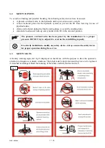
Страница 16: ...is only admitted when the vehicle is lifted are not running Never use the lift when safety devices are off line People the lift and the vehicles lifted can be seriously damaged if these instructions are not followed Figure 8 SAFETY AREA 6000 2000 1000 6 1 GENERAL WARNINGS The operator and the person in charge of maintenance must follow accident prevention laws and rules in force in the country whe...

Страница 17: ...ty holds on the lift in the elevated position The pressure overload valve has been preset by the manufacturer to a proper pressure DO NOT try to adjust it to overrun the rated lifting capacity 6 3 SAFETY SIGNS All safety warning signs ref fig 9 displayed on the lift are with the purpose to draw the operator s attention to dangerous or unsafe situations The labels must be kept clean and they have t...

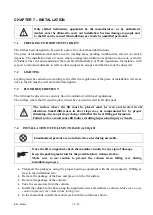
Страница 18: ...rmity with local regulations The surface where the lift must be placed must be even and leveled in all directions The surface where the lift must be placed must be even and leveled in all directions Small differences in floor slope may be compensated for by proper shimming Any major slope change will affect the level lifting performance Failure to do so could cause lift failure resulting in person...

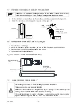
Страница 19: ...arm holes as shown in the figure 12 7 6 INSTALLATION OF POWER UNIT ref fig 13 Place the power unit onto the bracket on the back side of the column with the screws and washes attached as shown Secure it by tightening the screws Screw M20X60 Washer D 20 Locking washer D 20 Screw M12X40 Washer D 12 Locking washer D 12 Nut M12 Screw M8X20 Seeger D 16 Steel ball D 20 Screw M16X45 Washer D 16 Locking wa...

Страница 20: ...gs are in good condition Seal the fittings properly and connect the hoses as shown Tighten the hose fittings thoroughly Figure 16 INSTALLATION OF COLUMN TO BASE 7 9 MAKE THE ELECTRICAL HOOKUP The hookup work must be carried out by a qualified electrician Make sure that the power supply is right Make sure the connection of the phases is right Improper electrical hook up can damage motor and will no...

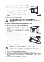
Страница 21: ...switch does not function properly unloosen its lever and adjust it at a proper position until the lift can reach at the desired height Tighten the screw after adjustment 7 10 2 ADJUSTMENT OF SAFETY HEIGHT LIMIT SWITCH ref fig 19 Place the lift at a height of 200 mm If the switch does not function properly unloosen its lever and adjust it at a proper height it is suggested to be lower 1 3mm than th...

Страница 22: ...3 HYDRAULIC SYSTEM FOR PROPER OPERATION Proper oil level in the tank refill if needed Raise the carriage to the full height and keep the motor running for 5 seconds Check all hoses connections to make sure no leakage Tighten the connections or reseal if necessary Check the carriage for reaching its maximum height Repeat the air bleeding of cylinders if necessary 7 12 4 LIMIT SWITCH FOR PROPER OPER...

Страница 23: ... in place tighten by securing the nut to the base Make sure that the lift is anchored with 8 pieces of M20X160 bolts at least 7 14 INSTALLATION OF FRONT COVER ref fig 20 Install the front cover as shown Figure 20 INSTALLATION OF FRONT COVER 7 15 CHECK WITH LOAD WARNING please follow carefully the instructions in the coming paragraph for avoiding damages on the lift Carried out two or three complet...

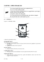
Страница 24: ...to get wet 8 1 CONTROLS Figure 21 CONTROL PANEL Controls for operating the lift are POWER SWITCH 1 The switch can be set in two positions 0 position the lift electric circuit is not powered the switch can be padlocked to prevent the use of the lift 1 position lift electric circuit is powered PILOT LAMP 2 It indicates that the lift electric circuit is powered LIFTING BUTTON 3 When pressed the motor...

Страница 25: ...fting button until reaching the desire height 8 3 STANDING Press the safety button to engage the nearest mechanical safeties Always ensure that the safeties are engaged before any attempt is made to work on or near the vehicle 8 4 LOWERING Lower the vehicle by pressing the lowering button the lift will take seconds to release the safety and then begin to descend under the weight of the load lifted...

Страница 26: ... unscrewing can reduce or increase the lowering speed Retighten the emergency lowering screw by turning it clockwise Remove the bolts from the safety hooks Refit the back covers onto the column and tighten the screws Figure 22 EMERGENCY LOWERING After manual lowering of the lift reset ordinary operating conditions Lift cannot be lifted if lowering valve is opened Bolt Bolt Emergency hand pump Emer...

Страница 27: ... a month using self cleaning clothes The use of water or inflammable liquid is strictly forbidden Be sure the rod of the hydraulic cylinders is always clean and not damaged since this may result in leakage from seals and as a consequence in possible malfunctions 9 2 PERIODIC MAINTENANCE Daily pre operation Check hydraulic connections and hoses for leaks Check safety lock audibly and visually while...

Страница 28: ...maximum pressure valve clogged or leaks Check and clean if dirty or replace if faulty The lowering valve does not close Check and clean if dirty or replace if faulty The suction tube or pump filter is dirty Check and clean if needed Presence of air in the hydraulic system Bleed the hydraulic system The lifting capacity is not sufficient The pump is faulty Check the pump and replace if needed Oil l...

Отзывы: