67
MATERIAL BLOWER ADJUSTMENTS (CONTINUED)
The floor speed can be increased using the basic controls until certain warning signs appear.
They include the following:
A.
CONSISTENT HOSE SHOCK
The Material Blower uses a large volume of air to blow the mulch material through the discharge
hose, which, at times, can become difficult for an operator to handle. Hose shock is usually due
to partial plugging around the discharge. When the material gets dislodged, the larger clumps are
shot through the hose and this action can make the hose jump significantly. If rough shock waves
become consistently tough on the operator at the end of the hose, the floor can be turned down
to smooth out the flow of material into the airlock. Lowering the engine RPM can also smooth out
hose shock by slowing down the air flow, but be careful not to lower the engine RPM too much,
as this can cause excessive plugging because there is not enough airflow to move the material.
When blowing wet, heavy material, slowing the airlock speed can smooth the material flow by
evenly introducing the material to the air steam. Generally, the airlock should not be run slower
than 10 RPM.
B.
EXCESSIVE AUTO-REVERSING
If the airlock starts to auto-reverse more than three times per minute, the airlock is being overfed
and the floor speed should be turned down. Excessive auto-reversing leads to lower material
feed when compared to a lower, properly adjusted floor speed. This condition will occur more
often with green, stringy mulch or less-processed material that contains larger chunks of wood
that the airlock may have to cut.
C.
BLOWER RELIEF
The blower on your machine has a relief valve in the air line to protect the blower against
a large back pressure that could build if the line becomes plugged. The relief valve, set for
12 psi (83 kPa), is located directly behind the blower in the engine area on the driver's side of
the machine. A blockage, temporary or otherwise, can trip the relief valve, which causes a loud
whining noise to be heard from the engine area. Occasional blowing off through the relief valve is
expected, as long as the machine can clear itself. However, if the relief valve goes off repeatedly
in a 10-second time span, then the discharge area or hose is in danger of becoming completely
blocked. The floor speed should be immediately reduced until the relief valve is not heard
consistently going off. Partial plugging most often occurs with less-processed material or if the
mulch is wet and dense.
D.
MATERIAL METERING GATE
The metering gate is a manually-operated gate located inside the rear of the hopper. It is a
vertical panel that can be moved up and down, as well as in and out, from the feed roll. When
changing the metering gate location, it is important to understand the three main material groups.
The closer the material is to Dry, Aged Material, the closer the gate should be to the feed roll, and
the farther it should be from the floor. The metering gate should be moved away from the feed roll
and closer to the floor, the closer the material is to Wet or Heavy Material, leaving Green Material
somewhere in-between the two. The better the material is, the less interaction the metering gate
should have; the heavier, wetter, and harder the material is, the more interaction the metering
gate needs.
Содержание A2548-001
Страница 4: ......
Страница 75: ...69 THIS PAGE LEFT BLANK INTENTIONALLY ...
Страница 82: ...76 Lubrication Chart Top View of Unit 1 3 2 9 1 12 16 14 6 17 10 8 15 5 7 4 11 1 1 13 5 3 4 ...
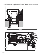
Страница 84: ...78 FINN MBH6 MATERIAL BLOWER TECHNICAL SPECIFICATIONS 166 78 31 57 67 91 97 86 ...
Страница 86: ...80 NOTES 80 ...
Страница 87: ...MBH6 MR1108 Rev A 81 WHEN ORDERING PARTS BE SURE TO STATE SERIAL NUMBER OF MACHINE MBH6 Parts Manual Model MR ...
Страница 90: ...MBH6 MR1108 Rev A 84 WHEN ORDERING PARTS BE SURE TO STATE SERIAL NUMBER OF MACHINE 7 6 5 9 4 7 6 3 8 1 2 ...
Страница 94: ...MBH6 MR1108 Rev A 88 WHEN ORDERING PARTS BE SURE TO STATE SERIAL NUMBER OF MACHINE 1 8 9 10 12 3 4 5 6 7 2 11 ...
Страница 102: ...MBH6 MR1108 Rev A 96 WHEN ORDERING PARTS BE SURE TO STATE SERIAL NUMBER OF MACHINE 2 4 1 7 2 3 5 6 ...
Страница 106: ...MBH6 MR1108 Rev A 100 WHEN ORDERING PARTS BE SURE TO STATE SERIAL NUMBER OF MACHINE 4 2 5 1 3 ...
Страница 108: ...MBH6 MR1108 Rev A 102 WHEN ORDERING PARTS BE SURE TO STATE SERIAL NUMBER OF MACHINE 7 2 10 3 1 8 9 4 5 6 ...
Страница 110: ...MBH6 MR1108 Rev A 104 WHEN ORDERING PARTS BE SURE TO STATE SERIAL NUMBER OF MACHINE 5 2 1 3 4 8 6 6 7 9 9 10 ...
Страница 120: ...MBH6 MR1108 Rev A 114 WHEN ORDERING PARTS BE SURE TO STATE SERIAL NUMBER OF MACHINE 12 10 8 11 4 1 5 14 15 7 6 3 2 9 ...
Страница 122: ...MBH6 MR1108 Rev A 116 WHEN ORDERING PARTS BE SURE TO STATE SERIAL NUMBER OF MACHINE 2 3 6 1 7 9 5 4 8 ...


