

Page 6
Testing the Sprayer
NOTE: It is VERY important for to test your sprayer with plain
water before actual spraying is attempted. This will enable you
to check for leaks without the possibility of losing any
expensive chemicals.
Fill the tank about 1/2 full with plain water and drive to the starting
place for spraying. When you are ready to spray, turn the boom valve
to the “on” position. This will start solution spraying from the tips of
the boom. The pressure will decrease slightly when the boom is
spraying. Adjust the pressure by turning the “ON/OFF” valve lever on
the bypass line valve. Make sure your pattern is sufficient. You may
down-pressure the system by ‘bypassing’ solution back into the tank.
This is achieved by opening the bypass valve. Regulating pressure is
done in this manner.
Read the operating instructions and initially begin spraying by closing
the ‘bypass’ valve (this is the valve marked Press. Adj. on your
manifold assembly) and opening the boom line valve (this is the
center valve on the manifold). This will enable the air in the line to be
eliminated (purged) through all the tips, while building pressure.
When everything tests all right (no leaks and good pressure), add the
desired chemicals to the mixture and water combination and start
your spraying operation. Adjust the pressure and spray as you did in
the testing procedure.
Conditions of weather and terrain must be considered when setting
the sprayer. Do not spray on windy days. Protective clothing must be
worn in some cases
Be sure to read the chemical label(s) before application!
Calibration
Chemical labels may show application rates in gallons per acre,
gallons per 1000 square feet or gallons per 100 square feet. You will
note that the tip chart shows 2 of these rating systems.
Once you know how much you are going to spray, then determine
(from the tip chart) the spraying pressure (PSI), and the spraying
speed (MPH).
Determining the proper speed of the pulling vehicle can be done by
marking off 100, 200 & 300 feet. The speed chart indicates the
number of seconds it takes to travel the distances. Set the throttle
and with a running start, travel the distances. Adjust the throttle until
you travel the distances in the number of seconds indicated by the
speed chart. Once you have reached the throttle setting needed,
mark the throttle location so you can stop and go again, returning to
the same speed.
Add water and proper amount of chemical to the tank and drive to
the starting place for spraying.
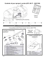
Using the Boom Nozzles
Four things must be considered before spraying with the boom.
How much chemical must be mixed in the tank.
Rate of spray (gallons per acre to be sprayed).
What pressure (p.s.i.) will be used.
Speed traveled (mph) while spraying.
Refer to the chemical label to determine your
chemical mixture
See the tip chart to determine the pressure to be
used. The chart will also show the speed used when
spraying.
Start the pump and open the valve to the boom
nozzles.
Check the spray pattern. Usually you can see the
coverage better on a solid concrete surface, such as
a driveway.
Raise or lower the nozzles so that you will have a
good coverage pattern. Generally the proper height
will be about 18 inches from the object(s) being sprayed.
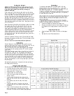
Speed Chart
Time Required in seconds to travel a distance of
Speed in M.P.H.
(Miles Per Hour)
100 Ft.
200 Ft.
300 Ft.
1.0
68 sec.
136 sec.
205 sec.
2.0
34
68
102
3.0
23
45
68
4.0
17
34
51
5.0
14
27
41
6.0
11
23
34
7.0
9.7
19
29
8.0
8.5
17
26
9.0
7.6
15
23
10.0
6.8
14
20
Operation
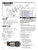
Your sprayer is equipped with (1) ON/OFF switch in the wire
assembly that you hook up to your battery. The “-” is the “ON”
position and the “o” is the “OFF” position for the switch. Make sure
the switch is depressed in the “-” position for operation.
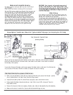
The pump is equipped with a pressure switch that is factory pre-set
for it to shut off at 45 p.s.i. This switch assembly is the ‘square box’
on the head portion of the pump.
Always fill the tank 1/2 full with water first and then add the chemical
slowly, mixing as you pour the chemical into the tank and then fill
the rest of the way. You may use the bypass in order to mix the
chemical and water.
The pumping system draws solution from the tank, through the
strainer/filter and to the pump. The pump forces the solution under
pressure to the handgun and/or boom nozzles.
Activate the handgun by squeezing the handle lever
Rotating the adjustable nozzle tip on the handgun will change
the tip pattern from a straight stream to a cone pattern (fine
mist)
Adjusting Pressure
When the bypass valve is closed, pressure is at the highest
point.
Opening the valve will decrease pressure.
Spray Tip Rate Chart (20" Spacing)
Tip
No.
Spray
Height
Pressure
(psi)
Capacity
(GPM)
Gallons Per Acre - Based on Water
1
MPH
2
MPH
3
MPH
4
MPH
5
MPH
6
MPH
8
MPH
AIXR11002VP
18"
15
.12
35.6
17.8
11.8
8.9
7.1
5.9
4.5
20
.14
41.6
20.8
13.8
10.4
8.3
6.9
5.2
30
.17
50.4
25.2
16.8
12.6
10.1
8.4
6.3
40
.20
59.6
29.8
19.8
14.9
11.9
9.9
7.4
Tip
No.
Spray
Height
Pressure
(psi)
Capacity
(GPM)
Gallons Per 1000 Sq. Ft. - Based on Water
1
MPH
2
MPH
3
MPH
4
MPH
5
MPH
6
MPH
8
MPH
AIXR11002VP
18"
15
.12
.41
.27
.20
.16
20
.14
.48
.32
.24
.19
30
.17
.58
.39
.29
.23
40
.20
.68
.45
.34
.27


