C. EXISTING HOLDER
1. For ease of installation, carefully remove the rupture
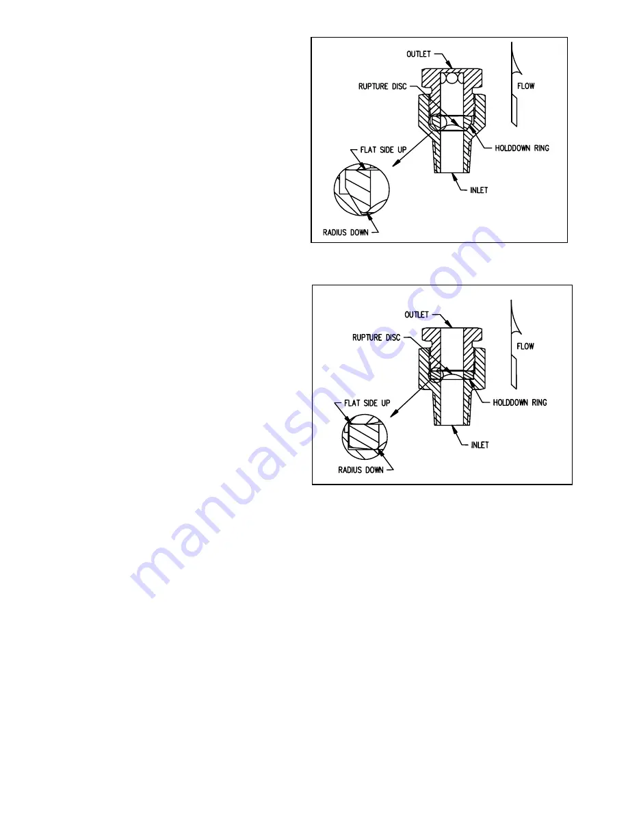
disc assembly from piping. (See Figures 3 and 4)
2. Separate rupture disc holder components.
3. Remove the rupture disc from its holder.
4. Inspect the seat area of the rupture disc holder. Look for
scratches, nicks, corrosion or deposits left from the media.
5. If necessary, clean the seat area with a solvent that is
compatible with your media. If this does not remove dirt,
hand polish the seat area with ScotchBrite, fine emery cloth
or #0000 steel wool. DO NOT MACHINE THE RUPTURE
DISC HOLDER! If scratches, nicks, corrosion or deposits
from the media cannot be removed by hand, contact the
factory.
D. ASSEMBLY
WARNING: Before attempting to assemble the rupture
disc and rupture disc holder, confirm that the seat area
of the rupture disc is designed to fit the rupture disc
holder.
1. Place rupture disc in the inlet of the rupture disc holder
with the dome pointing in the direction of flow.
2. Place the holddown ring on the rupture disc. Refer to
Figure 3 for proper orientation of 30
o
seat and Figure 4 for
proper orientation of flat seat.
3. Screw the outlet into place, hand tight.
4. Check holder rating and type located on the side of the
holder. Refer to Table 1 for torque values. Locate the table
with the corresponding type and rating. Locate burst pres-
sure. The column to the right contains the required torque in
ft-lbs.
5. Torque holddown nut to required torque.
Figure 4: Screw Type - Flat Seat
WARNING: Inversion of the holddown ring (installing
the ring upside down) may result in unexpected
performance characteristics, such as premature
opening or increased burst pressures.
Figure 3: Screw Type - 30
o
Seat


