background image

Speed Control 

The ATF 55E has electronic speed control so the speed of the 

blade remains constant regardless how much the motor is 

loaded. The speed of the motor should be set according to 

the type of material being cut. 


Figure 18 

18-a  Speed Control Knob 
18-b Pointer 
18-c Power Indicator 

Adjustment Settings 

Turn the speed control knob (18-a) so the speed indicator 

lines up with the pointer (18-b).  

Material Speed 

Soft wood products and veneer plywoods 

Hardwood products prone to burning 

when cut (i.e. cherry and maple) 

3-6 

Plastic laminate countertops 

Hard plastics 

3-5 

Soft plastics 

1-4 

Masonry and cementitious hardboard 

1-3 

Aluminum 4-6 
 

Power Switch 


Figure 19 

19-a  Plunge Release Lever 
19-b Power Switch (trigger) 
 
To prevent unexpected start-ups, the power switch has an 

integral safety interlock. Before the saw can be started, the 

plunge release must be engaged. 

1. 

Press up on the plunge release lever. 

2. 

Pull back on the power trigger. 

Bevel Setting 


Bevel cuts are made when the blade is tilted with respect to 

the sole plate.  

Figure 20 

20-a  Front Locking Knob 
20-b Rear Locking Knob 
20-c  Bevel Setting Gauge 
 

Setting the Bevel Angle 

1. 

Loosen the front (20-a) and rear (20-b) locking knobs. 

2. 

Tilt the saw to the desired angle as indicated on the 

bevel setting gauge (20-c). 

3. 

Re-tighten the two locking knobs.

Instruction Manual 

13 

Содержание ATF 55E

Страница 1: ...ATF 55E Circular Saw Instruction Manual Important Read and understand all instructions before using this tool ...

Страница 2: ...le plate 9 Adjusting the Blade Position 10 Replacing the Splinter Guard 11 Removing Replacing Adjusting the Riving Knife 11 Changing the Sawblade 12 Operation 12 Setting the Blade Depth 12 Speed Control 13 Power Switch 13 Bevel Setting 13 Dust Extraction 14 Basic Sawing 14 Making Plunge Cuts 15 Troubleshooting 16 Maintenance 17 Routine Maintenance 17 Changing the Motor Brushes 18 Accessories 19 Sa...

Страница 3: ...ng and use common sense when operating a power tool Do not use tool while tired or under the influence of drugs alcohol or medication A moment of inattention while operating power tools may result in serious personal injury Dress properly Do not wear loose clothing or jewelry Contain long hair Keep your hair clothing and gloves away from moving parts Loose clothes jewelry or long hair can be caugh...

Страница 4: ...rator If the blade becomes twisted or misaligned in the cut the teeth at the back edge of the blade can dig into the top surface of the wood causing the blade to climb out of the kerf and jump back toward the operator Kickback is the result of incorrect operating procedures or conditions and can be avoided by taking proper precautions as described below Maintain a firm grip with both hands on the ...

Страница 5: ...sets the depth of cut 2 b Plunge Depth Stop This sets the limit on how deep the blade will travel into the cut 2 c 90 degree Stop Screws The screws are for fine adjustment so the blade is at 90 degrees to the sole plate 2 d Sole Plate 2 e Dust Deflector Storage When the saw is used with a vacuum the dust deflector can be stored on top of the rear guide rail gib 2 f Hex Key Storage The hex key for ...

Страница 6: ...l shut down operation to protect the motor Thermal Overload Protection To protect the motor under excessive loading it is equipped with thermal overload protection This prevents the motor from being damaged due to overheating The motor is disabled until it has cooled down Wait 3 to 5 minutes for the overload protection to automatically reset Riving Knife Figure 5 5 a Riving Knife The riving knife ...

Страница 7: ...r latches upward step 7 2 as depicted by the two views of figure 7 4 Snap all four latches back to their flat position step 7 3 so they engage the stacking tabs item 6 c of the upper systainer Setup and Adjustments Setting up and Adjusting a New Saw WARNING Always disconnect the saw from the power supply before making any adjustments to the saw or installing or removing any accessory Follow this s...

Страница 8: ...edge of the guide rail has a replaceable rubber zero clearance strip The first time the saw is used with the guide rail this strip is trimmed to match the sawblade When trimmed to size this strip reduces chipping and tearout during normal cutting 8 ATF 55E Circular Saw Figure 9 9 a Blade Tooth 9 b Zero Clearance Splinter Guard black band If you have more than one tool that uses the same guid rail ...

Страница 9: ...od in half This is a precision adjustment Make sure the guide rail and workpiece are securely clamped The piece should be at least 20 mm thick and about 30 cm square inch thick by 12 inches square The thicker the piece the more accurate the adjustment will be For best results the material should have a consistent center such as Medium Density Fiberboard MDF plastic or solid lumber 2 Place the two ...

Страница 10: ...ted in the Blade Skew adjustment 3 Tighten the two bevel locking knobs but leave the rest of the screws loose The bevel locking knobs will hold the adjustments in place until the rest of the procedure is complete 4 Continue the rest of this adjustment by completing the Blade Skew adjustment described below After completing the Blade Skew adjustment return to step 5 below 5 After both parts of this...

Страница 11: ...wblade is properly adjusted before replacing the splinter guard Verify and or perform the Adjusting the Blade Position procedure described on page 10 before replacing the splinter guard Instruction Manual 11 Figure 14 14 a Splinter Guard 14 b Alignment Rib 14 c Friction Strips Replacement Procedure 1 Peel the original splinter guard away from the guide rail 2 As needed clean residual adhesive and ...

Страница 12: ... 1 Insert the new blade up through the bottom of the saw and place it on the arbor Make sure the blade teeth are pointing forward as shown 2 Place the arbor flange over the arbor and rotate it until the tabs line up with the slots in the arbor 3 Make sure the arbor and arbor flange are properly seated with one another 4 Insert and tighten the arbor screw Operation Setting the Blade Depth The ATF 5...

Страница 13: ...stics 3 5 Soft plastics 1 4 Masonry and cementitious hardboard 1 3 Aluminum 4 6 Power Switch Figure 19 19 a Plunge Release Lever 19 b Power Switch trigger To prevent unexpected start ups the power switch has an integral safety interlock Before the saw can be started the plunge release must be engaged 1 Press up on the plunge release lever 2 Pull back on the power trigger Bevel Setting Bevel cuts a...

Страница 14: ...e rib first and then the other works best Basic Sawing Intended Use The ATF 55 E is designed exclusively for the sawing of wood wood like materials and plastics With the special saw blades for aluminum offered by Festool this tool can also be used for sawing aluminum This tool should not be used for processing other materials The saw should not be converted or modified for any other form of use ot...

Страница 15: ...from your position 8 After the cut is complete release the power trigger and hold the saw steady until the blade comes to a complete stop Making Plunge Cuts Figure 24 24 a Guide Stop This guide rail accessory limits the travel of the saw and is necessary for safely making plunge cuts also shown in 25 a 24 b Clamping Knob Tighten this knob to secure the stop to the guide rail 24 c Direction Arrow T...

Страница 16: ...tools with a variable speed control When there is no load on the sawblade the pulsations of the motor cause the gears to rapidly engage and disengage called backlash and this is the sound you are hearing The saw makes wavy cuts Make sure the guide rail gibs are properly adjusted Inspect the blade for damage Make sure the sole plate is not rocking on the guide rail It is acceptable if the center of...

Страница 17: ...clean of all dust and debris Even soft wood dust can be abrasive over time Examine all moving parts for dust and debris Keep the bevel hinges figure 13 clean of dust using compressed air or cotton swabs If the hinges wear due to abrasive particles the saw will not perform optimally Keep the blade area and dust extraction ports clean of debris Debris can cause wear and reduce the effectiveness of t...

Страница 18: ...the motor 2 As necessary cut or remove any labels that may cover the seams between the motor and the access cover 28 c both sides 3 Remove the cover to expose the motor and brushes 4 Lift the terminal links 29 a and figure 30 straight up off the brushes and out of their sockets 29 c 5 Remove the two screws 29 b that secure the brushes to the motor housing Be careful not to drop the screws into the...

Страница 19: ...s grab free control for cutting aluminum and hard plastic Tooth Type ATB 48 teeth TCG 48 teeth TCG 56 teeth Hook Angle 12 4 5 Item Number 491 952 489 457 439 686 Notes ATB Alternate Top Bevel The ATB type blade slices through wood fibers first on one side and then on the other for clean cuts in natural and manmade materials TCG Triple Chip Grind The TCG type blade is designed to cut through hard m...

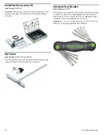
Страница 20: ...tead of the guide rail for making a rip using the edge of the workpiece as a reference Universal Tool Toolie Item Number 490 833 This single tool contains all of the drivers and keys necessary to adjust any Festool tool Exception Note that the arbor bolt on the saw uses a special hex key for changing blades Using the Toolie can damage the arbor bolt Contains 2 5 4 0 5 0 6 0 mm Hex Keys T10 T15 T20...

Страница 21: ...OL BE LIABLE FOR ANY CONSEQUENTIAL OR INCIDENTAL DAMAGES FOR BREACH OF THIS OR ANY OTHER WARRANTY EXPRESSED OR IMPLIED WHATSOEVER ALL WARRANTIES IMPLIED BY STATE LAW INCLUDING THE IMPLIED WARRANTIES OF MERCHANTABILITY AND FITNESS FOR A PARTICULAR PURPOSE ARE HEREBY LIMITED TO THE DURATION OF THREE YEARS Some states in the U S and some Canadian provinces do not allow the limitations on how long an ...

Отзывы: