Connect lines
1. Bring the solenoid valve into its installation position. Please note the direction of
flow. The permissible flow direction is marked by an arrow on the valve body. In
vacuum mode, connect up vacuum at output end.
2. Screw the valve plugs into the pipeline ends. Comply with the permissible tight
ening torques (
è
Fig. 6).
3. Establish the electrical connection. For this purpose use only the associated
socket type (
è
Fig. 7).
– Connect electrical cables to the socket.
– Attach seal to the electrical contacts.
– Put on plug and lock with fastening screw (tightening torque 0.3…0.5 Nm).
4. Connect the power supply.
7
Commissioning
Note
Commissioning only by qualified specialist personnel.
When incompressible media are used (e.g. neutral water) pressure surges arise
in the piping system because of the switching of the valve. Before commission
ing, check the compatibility of the devices in the system in order to avoid dam
age to them. If necessary adjust your application parameters.
Note the information on the rating plate.
Operate the solenoid coils only with upstream fuses.
Only start up the solenoid valve when it is fully installed and fitted.
Check the connection points for tightness
Before commissioning, check that the operating conditions and permissible limit
values have been observed (
è
Technical Data).
8
Operation
Warning
Risk of injury due to hot surface!
The valve can become hot while in operation.
Do not touch the valve during operation or immediately afterward.
Comply with the operating conditions.
Always observe the permissible limit values.
9
Maintenance and care
Every 6 months, check product from the outside for leakage and function.
Clean product regularly. The permissible cleaning agent is soap suds.
10
Disassembly
Warning
Risk of injury from combustion and chemical burns.
The media in the piping system and the valve can be hot and under pressure.
Medium residues can be in the product and escape when open or dismantled.
Allow the valve and piping to cool and depressurize them.
Wear specified protective equipment.
Note
Disassembly of the valve only by qualified specialized personnel.
1. De-pressurize the pipeline.
2. Switch off the power supply.
3. Empty the pipeline and valve completely.
– Ensure that no one is in front of the outlet opening.
– Catch discharging media in a suitable container.
4. Remove the solenoid valve from the pipeline (electrical socket connection,
mounting bracket and screws).
Replacement of the solenoid coil
In the case of repair, the solenoid coil can be replaced.
Dismantling:
1. Switch off the power supply.
2. Disconnect the electrical socket connection.
3. Leave the solenoid valve and solenoid coil to cool.
4. Loosen the retaining nut and take the magnetic coil and the O-ring from the
armature guiding tube.
Mounting:
1. Push the O-ring, the solenoid coil and the elements of the particular mounting
kit above the armature guiding tube.
2. Tighten the retaining nut (tightening torque
è
Technical Data).
11
Troubleshooting
Malfunction
Possible cause
Remedy
Solenoid valve
does not close
Solenoid valve faulty.
Replace solenoid valve.
Wrong mounting position or flow direction.
Correct mounting position.
Nominal voltage still applied.
Check electrical connection.
Solenoid valve
does not open
Solenoid coil or solenoid valve faulty.
Replace solenoid coil.
Replace solenoid valve.
Nominal voltage is interrupted or
insufficient.
Check voltage.
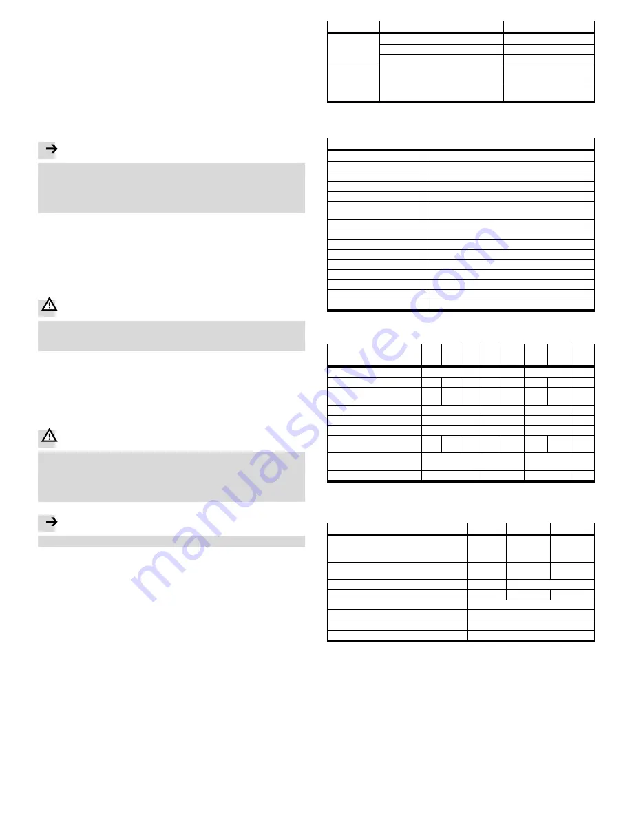
Fig. 4
12
Technical data
General
VZWF
Valve function
2/2-way valve, single solenoid, closed
Design
Diaphragm valve, forced
Actuation type
Electrical
Sealing principle
Soft
Assembly position
Magnet standing
Medium
Compressed air in accordance with ISO 8573-1:2010 [7:-:-],
Inert gases, Water, Neutral liquids
1)
Direction of flow
Non-reversible
Max. viscosity
[mm
2
/s]
22
Grade of filtration
[μm]
50
Temperature of medium
[°C]
–10...+80
Ambient temperature
[°C]
–10...+35
Protection class
IP65
Note on material for housing
Brass casting (standard), Stainless steel casting
Note on material for seals
NBR, EPDM, FPM
Note on materials for screws
High-alloy stainless steel
1)
Other media on request
Fig. 5
Connecting thread
G
¼
N
¼
G
y
N
y
G
½
N
½
G
¾
N
¾
G1
N1
G1¼
N1¼
G1
½
N1
½
G2
N2
Nominal diameter
[mm]
13.5
27.5
40
50
Flow factor K
v
[m
3
/ h]
1.8
2.2
2.5
7.5
11.0
20.0
22.5
28.0
Standard nominal flow
rate
[l/min]
1920
2350
2660
8020
11750
21370
23500
29900
Medium pressure
1)
[bar]
0…10
0…6
0…10
0…6
Switching times air on
2)
[ms]
130
275
620
1220
Switching times air off
2)
[ms]
180
290
1140
2140
Max. tightening torque
pipe connection
[Nm]
35
60
105
200
350
450
540
620
Max. tightening torque
coil fastening
[Nm]
2.0
4.0
Weight
[kg]
1.0
1.5
4.5
6.5
1)
Vacuum operation with p
abs
> 100 mbar possible
2)
Longer switching times with liquid media dependent on the viscosity
Fig. 6
Electrical data
VZWF-...1
VZWF-...2A
VZWF-...3A
Nominal voltage
– Direct current
– Alternating current (50/60 Hz)
[V DC]
[V AC]
24 (
_
10%)
–
–
110 (
_
10%)
–
230 (
_
10%)
Rated output for solenoid coil VACS-H1P
[W]
[VA]
11
–
–
19 / 16
1)
–
18 / 15
1)
Rated output for solenoid coil VACS-G2P
[W]
30
30
2)
Surge voltage capacity
[kV]
–
2.5
4.0
Duty cycle
[%]
100
Electrical connection
Device plug as per EN 175301-803, Form A
Connecting cable cross section
[mm
2]
0.75…1.5
Connection cable diameter
[mm]
5…9
1)
Switching power / holding capacity
2)
Operation with rectifier plug
Fig. 7


