– Voltage is applied at the solenoid coil: the arma-
ture releases the nozzle. The membrane pushes
the control piston against a spring in the actuator.
Exhaust port 3 is closed and the flow between
ports 1 and 2 is released.
– There is no voltage at the solenoid coil: the com-
pressed air supply from port 1 is closed. Port 2 is
connected with exhaust port 3. In doing so,
a downstream control unit can be vented.
Fig. 3 Circuit symbol
7
Assembly and installation
Note
Assembly and commissioning should only be carried out by qualified personnel.
7.1 Prerequisites
– The piping is unpressurised.
– Connecting cables and fittings are clean.
– The power supply is switched off.
7.2 Installation
1
2
3
4
5
6
Fig. 4
• Ensure that no condensed water collects in the valve.
• Slide solenoid coil
2
onto armature guide tube
4
. Check: sealing com-
pound
3
points to the valve body
5
.
• Slide spring washer
6
onto the armature tube guide.
• Tighten vent screw
1
.
– Tightening torque 5 Nm ± 20 %.
For outdoor applications
Note
Moisture, foreign matter and other contamination that enter the valve can damage
the product and limit functioning.
• Ensure that there is ventilation.
• Use exhaust protection.
• Catch exhaust air.
• With ½" und ½ NPT connection, use VABD-D3-SN-N12 exhaust protection.
• With ¼" und ¼ NPT connection, use VABD-D3-SN-G14 exhaust protection.
7.3 Pneumatic installation
– Do not use additional sealing material such as PTFE band or hemp.
– Do not use anti-friction coating or lubricant.
– Only use fittings with cylindrical threaded lugs and sealing rings or cutting rings.
– If port 1 (Fig. 5,
5
) with control signal < 2 bar is pressurised, supply auxiliary
energy > 2 bar to port 12 (Fig. 5,
6
).
– Recommendation: supply line cross section
6 mm.
7.4 Electrical installation
– Take suitable protective circuit measures to limit switch-off voltage peaks.
– Any polarity.
1
2
3
4
5
6
7
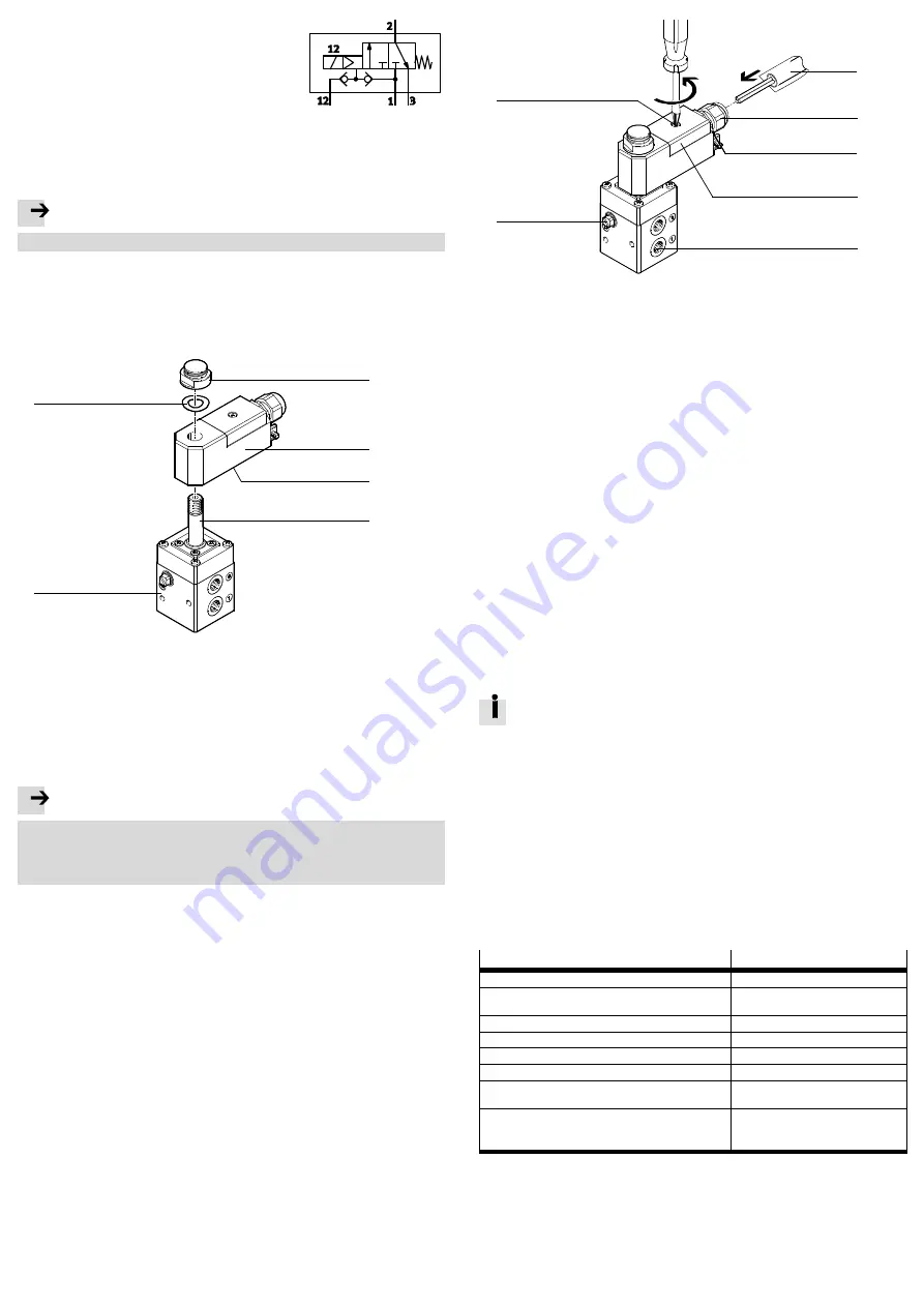
Fig. 5
1. Loosen the screws on terminal housing
7
and open cover
4
.
2. Disconnect cable connector
2
. Apply counter pressure to screw
3
.
3. Guide cable
1
through cable connector
2
and wire it to the terminals.
4. Connect the solenoid coil to the local potential equalisation via the inner or
outer protective grounding terminal.
5. Tighten cable connector
2
.
– Tightening torque 4.3 Nm ± 10 %.
6. Close the cover of terminal housing
4
and tighten screw
7
.
– Tightening torque 1.2 Nm ± 20 %.
Functional test
• After assembly, actuate the solenoid valve a few times and check for correct
function.
8
Commissioning
• After complete assembly and installation, check and document the safety function.
9
Service
– The product is maintenance-free.
– Repairs to the product are not permissible. In the event of malfunctions or fail-
ure, replace the product and let Festo know about the failure. Return defective
products to Festo.
9.1 Proof TestProof Test
The proof test consists of switching off the voltage at the solenoid valve and then
switching the voltage back on.
• Perform this test at least once every 7 years.
During the re-test, the safety of the application must be ensured.
1. Switch off the voltage at the solenoid coil.
2. Measure the time until the pressure at port 2 has completely decreased to the
ambient pressure (reaching the safe state).
The test is successful if the safe state is reached within the given time and
a downstream actuator has taken its intended position.
3. Switch on the voltage at the solenoid coil.
The test is successful if the pressure at port 2 has reached the original
value.
4. Check the valve externally (visual inspection).
The test is successful if no defect, leakage, or contamination is detected.
5. Document test results.
10
Technical data
General information
VOFC-LT-M32C
Mounting position
Any
Medium
Compressed air acc. to ISO
8573-1:2010 [7:-:-]
Temperature of medium
[°C]
–25…60
Ambient temperature
[°C]
–25…60
Storage temperature
[°C]
–20…40
Corrosion resistance class CRC
4
Degree of protection (in mounted state)
– VOFC-LT-M32C
IP65
Internal/external operating pressure
– VOFC-LT-M32C with port size
½†
– VOFC-LT-M32C with port size
¼†
[bar]
[bar]
2…8 / 0…8
1…8 / 0…8
Fig. 6


