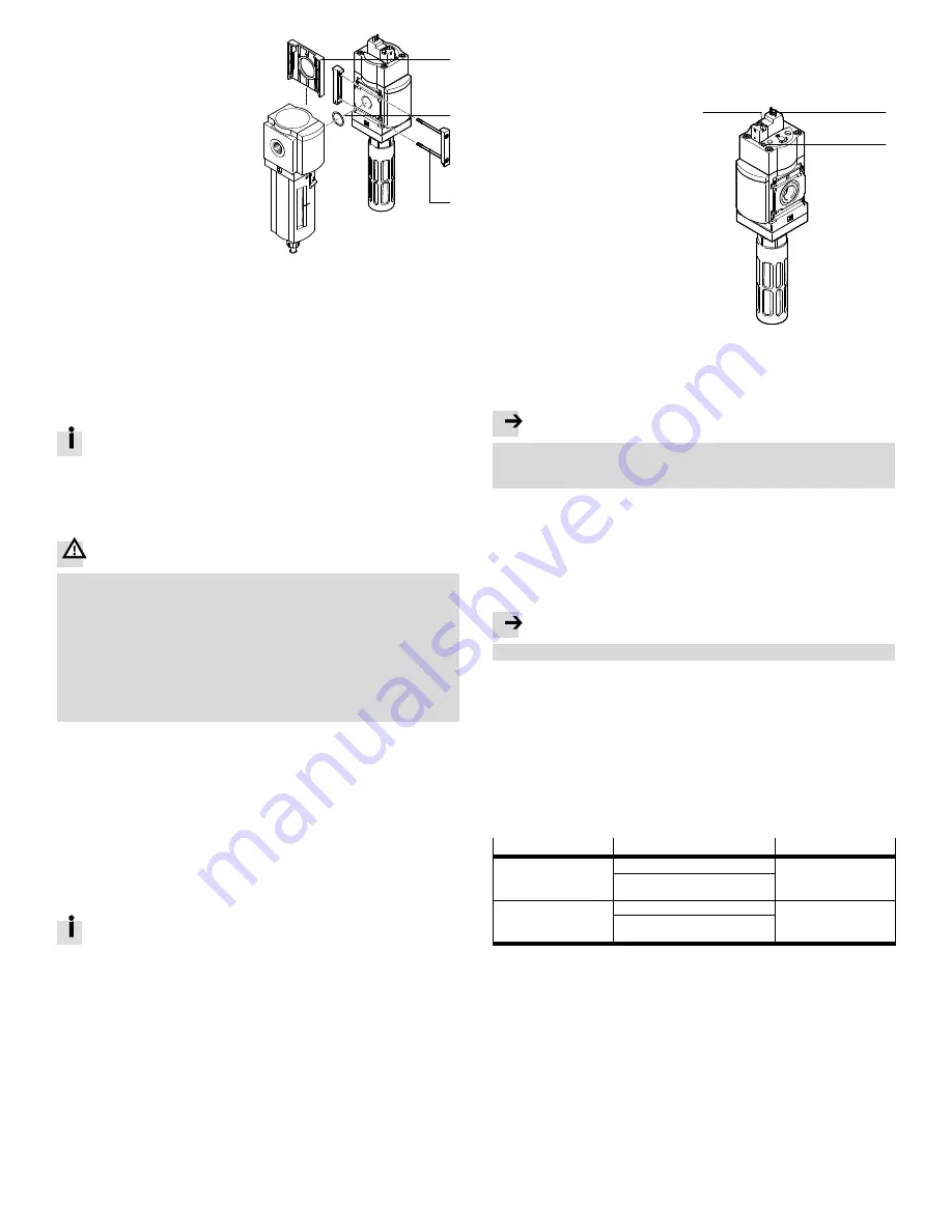
Assembly with MS-series service units
1. Slide any cover cap MS6-END
1
on
the side to be assembled upwards
and remove it.
2. Insert a seal
2
between the indi
vidual devices (module connector
MS6-MV in scope of delivery).
3. Place module connector
3
in
the slots of the individual devices.
4. Fasten the module connector with
two screws (MS6-MV scope of
delivery).
– Max. tightening torque 1.2 Nm.
Fig. 9
Assembly
1
2
3
6
Installation
6.1 Pneumatic installation
Port 1 and 2
If using fittings:
1. Note the permissible screw-in depth of the connecting thread is 10 mm.
2. Make sure that the compressed air lines are connected correctly.
3. Screw the fittings into the pneumatic ports using appropriate sealing material.
Port 3 (thread size G
¾
or NPT
¾
)
Exhausting a system using the MS6(N)-SV-...-C results in high noise levels.
Recommendation: use silencer
è
www.festo.com/catalogue.
1. Screw the silencer into pneumatic port 3.
2. Make sure exhaust is unhindered:
Both the silencer and port 3 must remain unblocked.
6.2 Electrical installation
Warning
Electric voltage – risk of injury due to electric shock.
Electrical connections must only be established when the voltage is discon
nected and by qualified personnel.
MS6(N)-SV-...-C-10V24/10V24P/10V24C/10V24D/V24/V24P
For the electrical power supply, use only PELV circuits in accordance with
IEC 60204-1/EN60204-1 (protective extra-low voltage, PELV).
MS6(N)-SV-...-C-V110/V230
Use only voltage sources in accordance with IEC 60204-1/EN60204-1.
Connect pilot solenoid valve (accessories
è
www.festo.com/catalogue).
7
Commissioning
7.1 Pressurising the product and piping system
1. Apply operating pressure p1 at MS6(N)-SV-...-C.
2. Switch on the supply voltage.
The outlet pressure p2 is built up slowly. The filling time “t” is set through
the main flow control valve attached to the cover (
è
Fig. 6,
7
).
The outlet pressure rises in accordance with the throttle point
è
Fig. 13.
If the preset pressure switching point (PSP) is reached, the main seat of
the valve opens
è
Fig. 14.
The downstream piping system is pressurised.
If the cover (tamper protection) is not mounted, the pressurisation pro
cess is started with the pressure build-up function through operation of
one of the manual overrides (
è
Fig. 6).
Reset manual override
è
7.3 Resetting the internal manual override..
7.2 Cover (tamper protection)
Use:
– In a safety-related system, the setting and control elements must be equipped
with a cover (tamper protection)
è
2.5 Further information.
If the cover (tamper protection) is mounted, the manual overrides cannot be
actuated.
– In a non-safety-related system, use of the cover (tamper protection) is optional.
7.3 Resetting the internal manual override.
A reset will be required if the internal manual override at the soft-start/quick ex
haust valve
8
was previously actuated without the cover (tamper protection)
being mounted.
Resetting can be performed through one of the following measures:
Issue of an electrical signal to pilot
solenoid valve
2
.
or
Actuation of the manual override at
pilot solenoid valve
1
.
Fig. 10 Resetting the internal
manual override
1
2
8
Activation of the internal manual override for feature -10V24C/-10V24D
Activate manual override
8
, if necessary, by removing the threaded pin.
Note
If the internal manual override is activated, it can only be reset through an elec
tric signal to the pilot control solenoid valve
2
, as the pilot control solenoid
valve has no manual override.
8
Operation
If the voltage drops, for example because the power supply is switched off,
the product exhausts the downstream piping system
è
Fig. 5.
After actuation of the internal manual override:
è
7.3 Resetting the internal manual override.
9
Dismounting
Note
Residual pressure must be eliminated before dismantling.
1. Switch off energy sources:
– operating voltage
– compressed air
2. Disconnect the relevant connections of the MS6(N)-SV-...-C.
10
Disposal
When the product reaches its maximum operating time or mission time, it must be
recycled in an environmentally friendly manner in accordance with applicable spe
cifications.
11
Fault clearance
Malfunction
Possible cause
Remedy
Valve switches abruptly.
Pressure switching point is too low.
Correct settings.
Main flow control valve is opened too
far.
Valve does not switch.
Pressure switching point is too high.
Correct settings.
Main flow control valve is not opened
far enough.
Fig. 11 Fault clearance
Repairs to the product are not permissible.
In the event of malfunctions or failure, replace the product and let Festo know
about the failure.
Return defective product to Festo.
12
Maintenance
The product is maintenance-free.
Cleaning
1. Switch off energy sources:
– operating voltage
– compressed air
2. If necessary, clean the product on the outside.
Soap suds (max. +50 °C), petroleum ether and all non-abrasive cleaning agents
may be used.


