


9
Operation
WARNING!
Danger of burns from hot housing surfaces.
Metallic housing parts can reach high temperatures during operation.
Contact with metal housing parts can cause burn injuries.
•
Do not touch metallic housing parts.
•
After the power supply is switched off, let the device cool down to room tem-
perature.
9.1
Master Control
–
Lowest priority: DIO operation (after Power ON and initialisation)
–
Medium priority: IO-Link operation (after established IO-Link communication)
–
Highest priority: HMI operation (unlocked pushbuttons)
9.2
Dimension Reference System
The correct positioning of the drive requires a defined dimension reference sys-
tem.
Linear drive system
–
Ref: reference end position (reference point for Lim
In
, Lim
Out
, Pos
Act
and Pos
Start Press
)
–
motor facing (default)
–
motor facing away
–
Lim
In
/Lim
Out
: end positions
–
Mech
In
/Mech
Out
: mechanical stops
–
Pos
Act
: current position
–
Pos
Start Press
: Start Press Position
.%!.
! .-..*%,
"+). #&')$).$((. #&).
"+).
.
.
.%!. .
! .-..&
#&). #&')$).$((. "+).
"+).
Tab. 2 Dimension Reference System for Linear Drive Systems
9.3
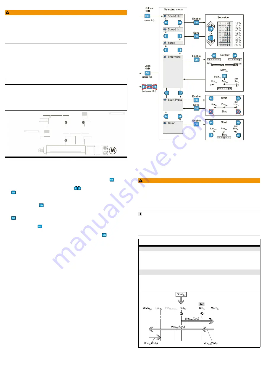
Display and Operating Components (HMI)
The display and operating components (HMI) can be used to perform the follow-
ing functions in the HMI menu:
–
Unlock pushbutton actuators (Unlock HMI), press and hold for 3 s
(Condition for IO-Link operation: IO-Link parameter 0x000C.4 = false)
–
Menu function with pushbutton actuators
select (selecting menu), press
–
Parameterise setpoint values Speed Out, Speed In and Force
(Set value: 10, 20, ..., 100% of maximum value
è
save (Save), press
–
Parameterise the position of the reference end position "Ref" (Set Ref) and
run the homing movement Mov
Ref
(Start
Ref
: Pos
Act
è
Lim
In
è
Lim
Out
), press
–
Run Start Press movement (Start/Stop) and save Start Press Position Pos
Start
Press
(Save), press
–
Execute Demo Run (Start/Stop)
–
Lock pushbutton actuators (Lock HMI), press and hold for 3 s
or no push-
button actuator input for 15 s
Fig. 7 HMI menu
9.4
Homing
During homing, the positions of the mechanical stops Mech
In
/ Mech
Out
are
determined in order to calculate the end positions Lim
In
(Ref)/Lim
Out
for the
dimension reference system.
Before the homing run is carried out, the drive is de-energised for a required re-
initialisation. Then the power supply is restored and the homing process starts.
WARNING!
Risk of injury due to unexpected movement of components.
When starting the homing run, the drive is disconnected from the power supply
for a short time. This can cause unexpected movements of the connected mechan-
ics and crush parts of the body.
•
Bring moving parts of the connected mechanical system into a safe position.
•
A new homing is only necessary if the reference end position Ref or the useful
range is changed.
•
When homing, the Start Press Position Pos
Start Press
is equated with the new
end position Lim
Out
.
Homing
Parameterise reference end position "Ref"
HMI:
–
Menu, Reference
è
9.3 Display and Operating Components (HMI)
IO-Link (acyclic device data):
–
motor facing (default): 0x0103.0, reference = false
–
motor facing away: 0x0103.0, reference = true
Control homing
HMI:
–
Start
Ref
: menu, reference
è
9.3 Display and Operating Components
IO-Link (acyclic device data):
–
Start
Ref
:
0x0104.0, Execute Mov
Ref
= true
Tab. 3 Parameterise and Control Homing
9.5
End-to-end Operation
In end-to-end operation with or without press function, the unit can be moved
between the end positions Lim
In
/Lim
Out
.