


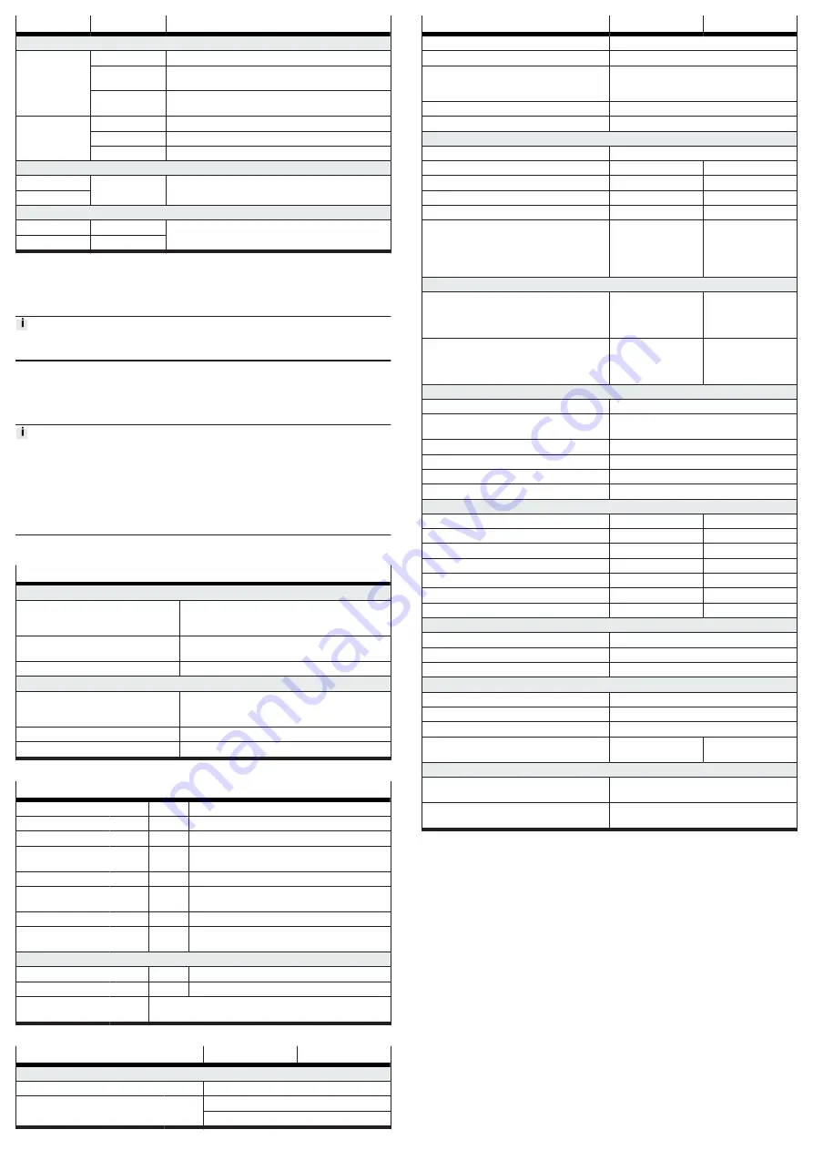
LED
LED status
Event/state
Behaviour in the operating phase
OK
off
Hardware is not ready for operation; an error is pending.
flashing green
Hardware is ready for operation; but the “Enable” signal is
not pending.
green
Normal operating status; hardware is ready for operation;
“Enable” signal is pending.
ERROR
off
no error, no warning
flashing red
A warning is reported.
red
An error is reported.
Behaviour during waving
OK
simultaneous
flashing
Wink function active (for visual identification, can be acti-
vated via the webserver)
ERROR
Behaviour with errors in the firmware update phase
OK
off
Firmware update was cancelled due to an error.
ERROR
flashing red
Tab. 16
9
Cleaning, repair and disposal
Clean the outside of the product with a soft cloth.
Repair or maintenance of the product is not permissible. If necessary, replace the
complete product.
Observe the local regulations for environmentally friendly disposal of electronic
components.
10
Technical data
Further technical data can be found in the following documents:
• Detailed technical data for the STO interface
è
Description of the STO safety
function EMCA-EC-S1-…
• Additional technical data
è
Device and function description EMCA-EC-SY-…
• Requirements for complying with the certified UL conditions if the product
is operated in the USA or Canada can be found in the separate UL special
documentation.
Technical data, safety engineering
Approval information, safety engineering
CE
Type-examination
The functional safety engineering of the product has
been certified by an independent testing body, see EC-
type examination certificate
Certificate issuing authority
TÜV Rheinland, Certification Body of Machinery, NB
0035
Certificate no.
01/205/5514.01/21
UKCA
Type-examination
The functional safety engineering of the product has
been certified by an independent body, see UK-type
examination certificate
Certificate issuing authority
TUV Rheinland UK Ltd, UK Approved Body No. 2571
Certificate no.
01/205U/5514.00/22
Tab. 17: Approval information, safety engineering
Safety reference data and safety specifications
Safety function
STO
Safe Torque Off (safe torque off)
Category
3
in accordance with EN ISO 13849-1
Performance Level
PL d
in accordance with EN ISO 13849-1
Safety Integrity Level
SIL 2
in accordance with EN 61800-5-2 (safety integrity
level)
SIL Claim Limit
SILCL 2
in accordance with EN 62061 (SIL claim limit)
DC
avg
[%]
90
Average diagnostic coverage
(average diagnostic coverage)
SFF
[%]
>
90
Safe Failure Fraction (safe failure fraction)
PFH
D
[1/h]
1 x 10
-9
Probability of dangerous failure per hour
(probability of dangerous failure per hour)
T
Proof Test Interval
[years]
20
Test interval
Service life
[years]
20
in accordance with EN ISO 13849-1
Type test
The STO function has been certified by an independent testing
body. EMCA certificate
Tab. 18: Safety reference data and safety specifications
General technical data
EMCA-…-S-…
EMCA-…-M-…
Environmental and operating conditions
Mounting position
any
Ambient temperature
[°C]
at nominal power: 0 … 20
with power reduction 1.75% per °C: 20 … 50
General technical data
EMCA-…-S-…
EMCA-…-M-…
Storage temperature
[°C]
–25 … +70
Relative humidity at 25 °C
[%]
0 … 95 (non-condensing)
Degree of protection EMCA… (without
S1)
EMCA…-S1
IP54
IP65; motor shaft IP54
Protocol
CANopen
Communication profile
CiA 402, FHPP
Power supply [X4]
Nominal voltage
[V DC]
24
Permissible voltage fluctuations
[%]
± 20
–
Nominal current
[A]
6.9
7.2
Peak current
[A]
10.2
10.3
Rotor position encoder
absolute single-turn
absolute multi-turn
Resolution
[Bit]
12 (4096 increments
per revolution)
12 bits (4096 incre-
ments per revolution)
and 4294967729 (±
2147483648) revolu-
tions; 32 bit
Absolute encoder operating duration (at medium ambient temperature)
without external battery
Note: the maximum storage period depends on
the charge status of the internal capacitor, the
ambient temperature and ageing effects.
–
3 days (worst case);
maximum of 7 days
(best case)
with external battery
Note: the maximum service life of the battery
depends on the state of charge, ambient temper-
ature and ageing effects.
–
maximum 6 months
Digital inputs/outputs
Switching logic inputs/outputs
PNP (positive switching)
Characteristics of digital logic outputs
freely configurable in some cases
not galvanically isolated
Peak current to digital logic outputs
[mA]
100
Characteristics of logic inputs
galvanically connected to logic potential
Specification of logic inputs
based on IEC 61131-2
Operating range of logic input
[V DC]
24
Motor data
Nominal power
[W]
120
150
Nominal torque
[Nm]
0.37
0.45
Nominal rotational speed
[rpm]
3100
3150
Max. rotational speed
[rpm]
3500
3300
Mass moment of inertia of rotor
[kgcm
2
]
0.175
0.301
Permissible axial shaft load
[N]
60
60
Permitted radial shaft load
[N]
100
100
Holding brake (only EMCA-EC-…-…B)
Brake holding torque
[Nm]
1
Brake power consumption
[W]
9
Mass moment of inertia, brake
[kgcm
2
]
0.021
Max. line lengths (for ensuring EMC conformity)
Power supply cable
[m]
£
30
STO and I/O interface
[m]
£
30
Limit/reference switch, battery
[m]
£
3
Product weight (without [B], without
[M])
1)
[g]
1900
2260
Product conformity and approvals
CE marking (declaration of conformity
in accordance with EU Machinery Directive
in accordance with EU EMC Directive
2)
Approvals
3)
RCM (Regulatory Compliance Mark)
3)
c UL us – Recognized (OL)
3)
1) Holding brake [B] +350 g, multi-turn absolute displacement encoder [M] +25 g
2) The device is intended for use in an industrial environment. Measures may be required in residential areas
for interference suppression.
3) only valid for product variants with corresponding identification
Tab. 19


