


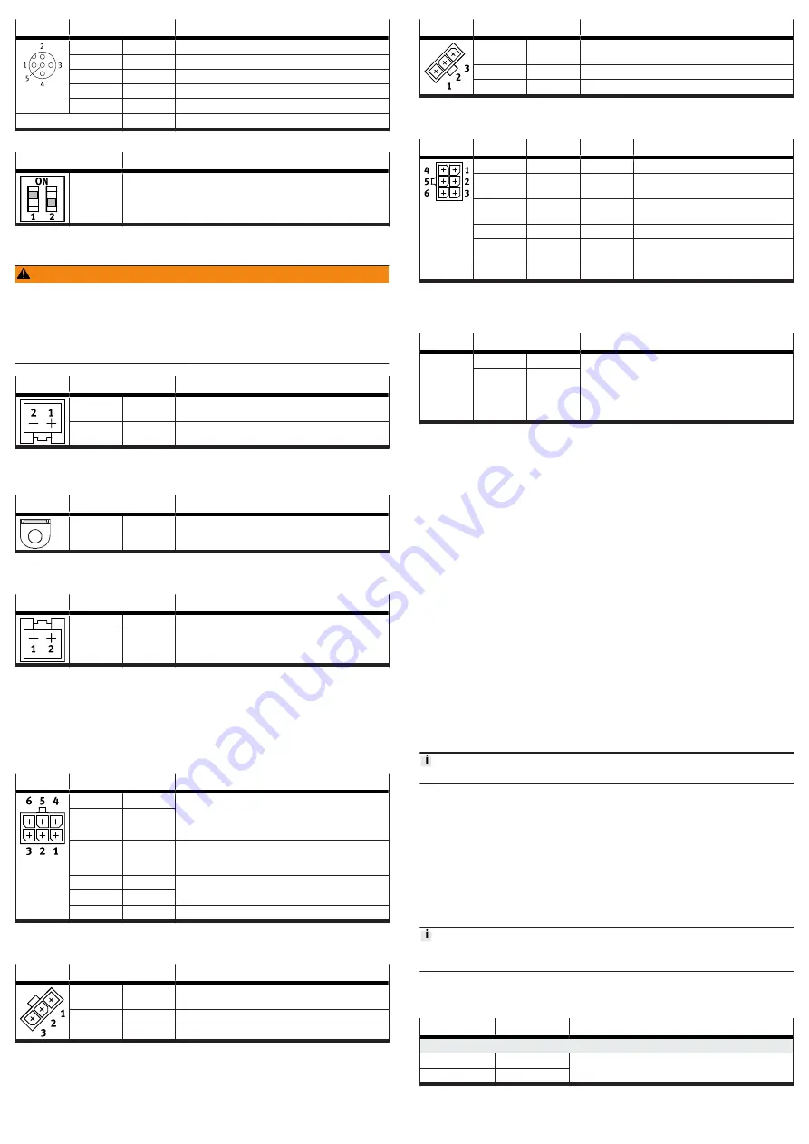
[X3]
Pin
Description
1
CAN_SHLD
Shield, capacitive connection to housing
2
NC
not connected
3
CAN_GND
CAN bus reference potential
4
CAN_H
CAN bus high
5
CAN_L
CAN bus low
Housing
Shield/FE
Shield/functional earth
Tab. 6
DIL switch
Function
S1.1
Terminating resistor for CAN bus (120 Ω); ON = ON, OFF = OFF
S1.2
reserved
Tab. 7
6.4
Power supply [X4]
WARNING
Risk of injury due to electric shock.
• For the electrical power supply, use only PELV circuits in accordance with IEC
60204-1/EN 60204-1 (Protective Extra-Low Voltage, PELV).
• Observe the general requirements of IEC 60204-1/EN 60204-1 for PELV circuits.
• Only use voltage sources that ensure a reliable electric separation from the
mains network in accordance with IEC 60204-1/EN 60204-1.
[X4]
Pin
Description
1
+24 V DC
Power supply (logic and load voltage)
+19.2 V DC … +28.8 V DC
2
0 V
GND, reference potential
Tab. 8
If a shielded supply cable is used, the cable shield can be connected to the
functional earth connection (flat plug).
Flat plug Pin
Description
–
FE
Optional connection for the cable shield
Mating connector: flat connector sleeve (6.3 x 0.8 mm
2
)
Tab. 9
6.5
Braking resistor [X5]
[X5]
Pin
Description
1
ZK+
Connection for the external braking resistor R
BR
6 Ω; the
braking resistor CACR-LE2-6-W60 from Festo is suitable.
2
BR-CH
Tab. 10
6.6
STO interface [X6]
The STO safety function is described in detail in the EMCA-EC-S1-… document. The
STO function should only be used in the manner described in this document.
Recommendation for initial motor start-up without safety engineering:
–
minimum circuitry with emergency stop switching device
–
two-channel switch-off via control inputs STO1 [X6.4] and STO2 [X6.5]
[X6]
Pin
Description
1
NC1
Acknowledgement contact:
–
potential-free
–
low impedance if the STO function has been
requested and activated via 2 channels.
2
NC2
3
+24 V DC
LOGIC OUT
Logic voltage output (from [X4.1]), reference potential
(0 V) is pin [X6.6] or [X4.2] (internally bridged)
Not overload-proof! Max. 100 mA permissible.
4
STO 1
Control inputs for STO function
5
STO 2
6
GND
Reference potential 0 V
Tab. 11
6.7
Limit/reference switch [X7], [X8]
[X7]
Pin
Description
1
+24 V DC
Voltage output 24 V for supply of the reference or limit
switch 1 (configurable with FCT, not short-circuit proof).
2
Switch 1
Signal input for reference switch or limit switch 1
3
GND
Reference potential 0 V
Tab. 12
[X8]
Pin
Description
1
+24 V DC
Voltage output 24 V for supply of the reference or limit
switch 2 (configurable with FCT, not short-circuit proof).
2
Switch 2
Signal input for reference switch or limit switch 2
3
GND
Reference potential 0 V
Tab. 13
6.8
I/O interface [X9]
[X9]
Pin
Type
1)
Name
Description
1
DOUT
Ready
signals the ready status
2
DOUT
configu-
rable
Output behaviour configurable with FCT
3
–
+24 V DC
Output 24 V DC; looped through from
[X4.1]
4
DIN
Enable
Enable/block closed-loop controller
5
DIN
Sample
Signal for saving the actual position
(Flying measurement)
6
–
GND
Reference potential 0 V
1) DIN = digital input; DOUT = digital output
Tab. 14
6.9
External battery [X10] - only EMCA-EC -...- 1TM
[X10]
Pin
Description
1
B
Connection for external battery (position changes are
recorded for a maximum of 7 days (best case) without
supply voltage and without battery (after charging for
approx. 24 hours)). With the EADA-A-9 battery from
Festo, the duration can be extended to a maximum of
6 months.
2
Battery –
(GND)
Tab. 15
6.10
Ensuring the IP degree of protection
–
Comply with the requirements for securing the IP degree of protection
è
Device and function description, EMCA-EC-SY-….
7
Commissioning
The product communicates with a connected PC with the TCP/IPv4 protocol.
Establishing network connection – example “point-to-point connection”
Requirement:
–
The PC is configured as a DHCP client (usually standard for PCs).
–
The EMCA is configured as a DHCP server (factory setting).
–
At initial commissioning connect the EMCA directly to the PC.
Factory setting
DHCP server: active
IP address: http://192.168.178.1
Subnet mask: 255.255.255.0
Gateway: - (a gateway is not assigned.)
Web servers
The integrated web server provides read access to an English-language website.
FCT (Festo Configuration Tool)
The EMCA plug-in for the Festo Configuration Tool (FCT) supports all the steps
necessary for commissioning of the device.
Observe the documentation for the product
Before switching on the power supply:
Check installation:
–
Check all connections.
Check readiness for operation
1. Make sure that controller enable signal is switched off (pin X9.4).
2. Switch on the power supply. The OK LED on the front panel of the device
should now flash green.
If the OK LED stays off, the device is not ready for operation. If the ERROR-LED
shows red, an error is reported and the cause of the error must be remedied.
Further steps for commissioning
è
Help for the EMCA plug-in and device and
function description EMCA-EC-SY-…
8
Diagnostics and fault clearance
Information on the bus status LED
è
Description for the device profile.
LED
LED status
Event/state
Behaviour during the switch-on phase
OK
flashing green
Start-up phase, bootloader active
ERROR
flashing red


