


Note
Unsuitable mounting techniques can reduce the service life of the ELGR/ELGG
considerably.
Make sure that the mounting components are outside the positioning range of
the slide (e.g. projecting slot nuts).
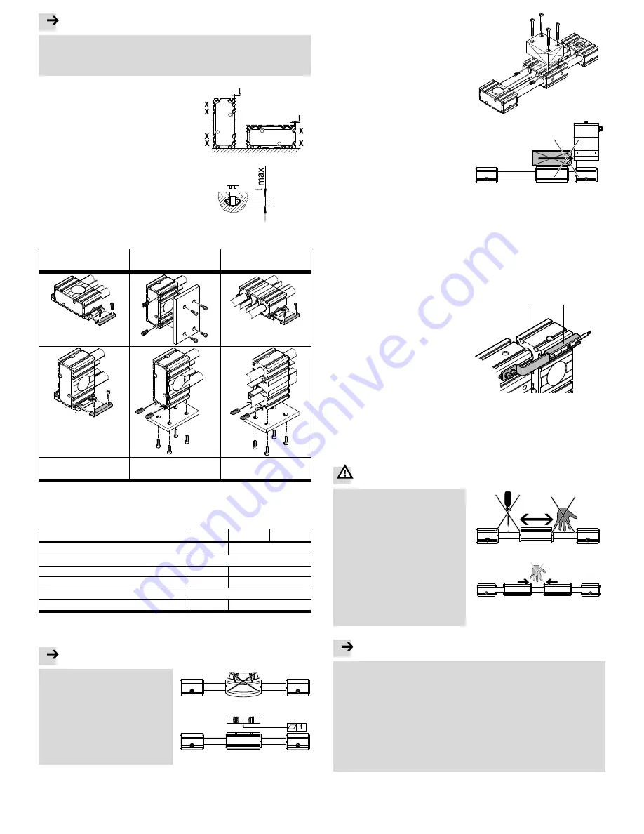
Take into account the asymmetric
geometry of the ELGR/ELGG.
Depending on the orientation, the
slide unit or bearing cap projects
beyond the contour by the dimension
l (observe position X of the proximity
sensor).
Fig. 4
Observe the screw-in depth t
max
when using slot nuts (
è
Fig. 7).
Attach the ELGR/ELGG and, if avail
able, the central support (
è
Fig. 6).
Fig. 5
Please select the corresponding accessories from our catalogue
(
è
www.festo.com/catalogue)
Profile mounting
with MUE
Slot nut mounting with
NST
Central support with
MUE/NST (ELGG only)
Profile mounting in the
groove
7
Slot nut mounting in the
slot
7
Profile or slot nut
mounting in the slot
7
1)
1)
Attach the central support centrally, otherwise the stroke will reduce
Fig. 6
Tighten the mounting screws evenly.
The tightening torque is summarised in the following table.
ELGR/ELGG-...
35
45
55
Screw
M3
M5
Centring sleeve
ZBH-7
Slot nut
NST-3-M3
NST-5-M5
Screw-in depth t
max
(
è
Fig. 5)
[mm]
3.8
6
Projection l (
è
Fig. 4)
[mm]
2
Tightening torque
[Nm]
1
5
Fig. 7
5.2 Installation of the payload
Note
If the aluminium slide is bent against a
curved payload, the service life of the
guide will be reduced.
Make sure that the mounting
surface of the payload is even to
within t ≤ 0.01 mm.
Fig. 8
Place the payload so that the pull-
out torque from the force (parallel to
the axis of motion) and lever arm re
mains low.
Fasten the payload to the slide with
4 screws and slot nuts as well as
centring elements, if needed.
(Tightening torque
è
Fig. 7).
Fig. 9
For load geometries with projection in
the longitudinal direction of the slide:
Make sure that the payload does not
strike against the motor or bearing
cap and, in the case of the ELGG,
against the central support.
Fig. 10
5.3 Electrical installation
To protect the end positions against uncontrolled overtravel:
Check whether additional hardware proximity sensors are necessary.
If inductive proximity sensors are used as hardware limit switches:
Use proximity sensors with normally-closed function.
The normally closed function protects the ELGR/ELGG against overrunning the
end position if the proximity sensor cable is broken.
Use proximity sensors that correspond to the input of the controller being used.
If proximity sensors are used as reference switches:
Attach the kit with switch lug (S) and
sensor bracket (L) according to the
assembly instructions (
è
Catalogue
specifications,
www.festo.com/catalogue).
Avoid external influences from
magnetic or ferritic parts in the
vicinity of the proximity sensors
(minimum distance of 3 mm).
Fig. 11
(S)
(L)
To avoid contamination:
Select the appropriate slot covers from our catalogue (
è
Catalogue specifica
tions, www.festo.com/catalogue).
6
Commissioning
Warning
Payloads can cause personal injury
and material damage (risk of
crushing).
Make sure that, in the positioning
range:
– nobody can place his/her hand in
the path of the moving components
(e.g. through a protective guard),
– there are no foreign objects in the
path of the moving components.
It should not be possible to touch
the ELGR/ELGG until the load has
come to a complete standstill.
Fig. 12
Note
Incorrect specification values of the braking ramp in STOP situations (e.g.
EMERGENCY STOP, Quick Stop) result in an overloading of the linear axis and can
destroy it or drastically reduce its service life.
Check the settings for all braking ramps in the controller or the higher-order
control system (deceleration values and jerk).
Taking the travel speed, moveable load and mounting position into account,
make sure that the delay values (brake delay and delay times) are set in such
a way that the maximum drive torque or feed force of the linear axis used is
not exceeded.
Use the “Positioning Drives” sizing software from Festo to design the linear
axis (
è
www.festo.com).


