Out A/Out B
1)
1)
Depending on configuration
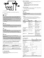
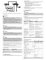
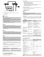
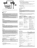
Fig.8: DNCE−LAS with clamping unit and valve control on the SFC−LACI
6
Commissioning
Warning
Uncontrolled moving parts can cause injury to people in the vicinity of the
DNCE−LAS−C.
· Make sure that the electric cylinder with the DNCE−LAS clamping unit is
logically controlled in a correct manner. The clamping mechanism can be
damaged as a result of incorrect control. This can result in the piston rod
suddenly advancing or retracting.
· Make sure that, in the traversing area, no one can reach into the direction of
motion of the moving parts and that no foreign bodies can get in.
Note
The actuators will be considerably accelerated.
· Make sure that the DNCE−LAS is not moved when releasing the clamp.
The movement when the clamp is released generates forces that can destroy
the electric cylinder or can wear out the clamping unit.
Note
The actuators may perform sudden unexpected movements.
· Avoid exceeding the static holding force (
see
Technical specifications).
The clamping unit is not suitable for dynamic braking. The dynamic forces
must not exceed the static holding forces.
Note
The reference travel cannot be executed in the mechanical end position.
· Make sure that the piston rod is not moved into the mechanical end position.
Otherwise the DNCE−LAS cannot be referenced. To remedy this: unlock the
clamping unit (using the transport screw if necessary) and push the piston rod
into the middle stroke position.
· Make sure that the DNCE−LAS has reached the parking position during the
motion sequence before exhausting and clamping the clamping unit.
· Observe the commissioning instructions for the DNCE−LAS in the operating
instructions (
è
Commissioning DNCE−LAS).
· Make sure that the operating pressure on the clamping unit is as follows:
To release the piston rod
To clamp the piston rod
Min. 3 bar
Max. 0.5 bar
Lower pressures will impair the release of
the clamp hold
Excessively long and narrow pipes between the valve
and the DNCE−LAS−C will slow down the clamping.
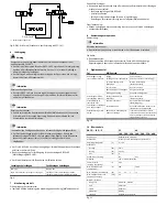
Fig.9
7
Operation
If there is a change in the work load mass:
· Compare the specified safe loads with your actual application
(
è
Technical specifications).
Checking the clamp hold:
· Check regularly or after a sudden power failure to make sure that clamping
takes place correctly without a working load as follows:
deactivate control of the DNCE−LAS
Vent the clamping unit
Try to move the piston rod by hand in the stroke direction.
The piston rod must not move any more than the amount of axial play
(
è
Technical specifications").
With all applications:
· Keep the piston rod from becoming dirty. Oil and grease residues on the piston
rod reduce the clamping capacity.
8
Disassembly and repairs
Disassembly:
Note
The actuators may perform sudden unexpected movements.
· Make sure that the electric cylinder is deactivated and the clamping unit
exhausted.
If necessary:
· Recommendation: Return the product to our repair service for overhaul. This
ensures that special attention will be paid to the necessary fine adjustments and
inspections. The clamping unit does not usually require maintenance.
9
Eliminating malfunctions
Malfunction
Possible cause
Remedy
Piston rod moves in spite
f l
i
i b i
Wear
Send to Festo
p
of clamping unit being
exhausted
Permanent manual unlocking
Remove screw from connection
3
exhausted
Operating pressure at the
clamping unit too high
Reduce operating pressure
(
è
Technical specifications)
Mass too large
Reduce the mass
Piston rod is dirty
Clean the piston rod
Incorrect actuation
Check actuation
Piston rod clamped even
though clamping unit is
pressurized
Insufficient operating
pressure on the clamping
unit
Increase operating pressure
(
è
Technical specifications)
When the clamping unit
is pressurized, the piston
rod moves at high speed
Controller deactivated
Always move to the end position in a
controlled manner
(
è
Commissioning)
rod moves at high speed
into the end position.
Malfunction in the DNCE−LAS
Check the DNCE−LAS for malfunctions
(
è
DNCE−LAS operating instructions)
No reference travel
possible
DNCE−LAS at mechanical end
position when switched on
Deactivate controller and unlock
clamping unit (e.g. with transport
screw)
Push piston rod by hand into middle
stroke position
Fig.10
10
Technical specifications
DNCE−...−LAS−...−C
32
40
100 200 320 100 200 320 400
Constructional design
Spring−loaded clamping profile
Operating medium
Dried compressed air, lubricated or
unlubricated
Ambient temperature
[°C]
0 ... +60
Operating pressure
Loosening
[bar]
min. 3
Clamping
[bar]
max. 0.5
Maximum
[bar]
8
Pneumatic connection
M5
G
Á
Á
Ambient conditions
Piston rod must be free of oil and grease
Closing time (releasing and clamping)
[s]
0.02
Max. static holding force of clamping unit
[N]
600
1000
Max. effective load (vertical operation)
[kg]
1.5
1.5
1
1,5
Max. axial backlash with piston rod
clamped and without load
[mm]
0.5
Materials (clamping unit)
Housing, cover
Anodised aluminium
Piston
Polyacetate
Spring
Spring steel
Clamping jaws
Brass
Seals
Nitrile rubber, polyurethane
Fig.11


