


2. Connect cables in accordance with the following table:
Insu-
lated
wire
1)
Proximity sensor,
flange side
Proximity sensor,
cap side
BN
Digital Inputs 24V
Digital Inputs 24V
BU
Digital Outputs 0V
Digital Outputs 0V
BK
Digital Inputs DI0
Digital Inputs DI1
1) wire colour when using connecting cables in accordance with accessories
è
www.festo.com/cata-
logue
Tab. 4 Pin allocation for cables to proximity sensors
6.4
Software installation
The software must be installed manually from the included USB memory stick.
The USB memory stick has the following data:
–
URCap
–
User documentation
System requirements for hardware and software:
•
Robot UR3/UR5/UR10: from software version PolyScope CB 3.8.0
•
Robot UR3e/UR5e/UR10e/UR16e: from software version PolyScope SW 5.0.0
Always use the current software version
è
Older software versions may have a different appearance from this user docu-
mentation.
1. When the system is started, insert the USB memory stick into the control unit.
2. Press the "Menu" button at the top right of the header.
3. Select "Settings" menu item.
4. Select the "URCaps" button in the menu item "System".
5. Press the "+" button at the bottom left.
6. Select and open "FestoGripperDHEFURCap-XXXurcap".
X.X.X corresponds to the version number of the software e.g. 1.0.4
7. Press the "Restart" button at the bottom right.
Ä
The URCap is installed and can be used.
Fig. 4 Sample settings
6.5
Configuration of the software
Configuration of adaptive shape gripper
1 Select gripper
2 Activate/deactivate proximity
sensor
3 Default values
4 Activate/deactivate URCap
5 Activate/deactivate URCap logging
Fig. 5 Configuration of adaptive shape gripper
.
. Adjustments are necessary if the cables of the
components were installed differently.
3. Adjust proximity sensors. The LED of a proximity sensor must be on at the cor-
responding end position.
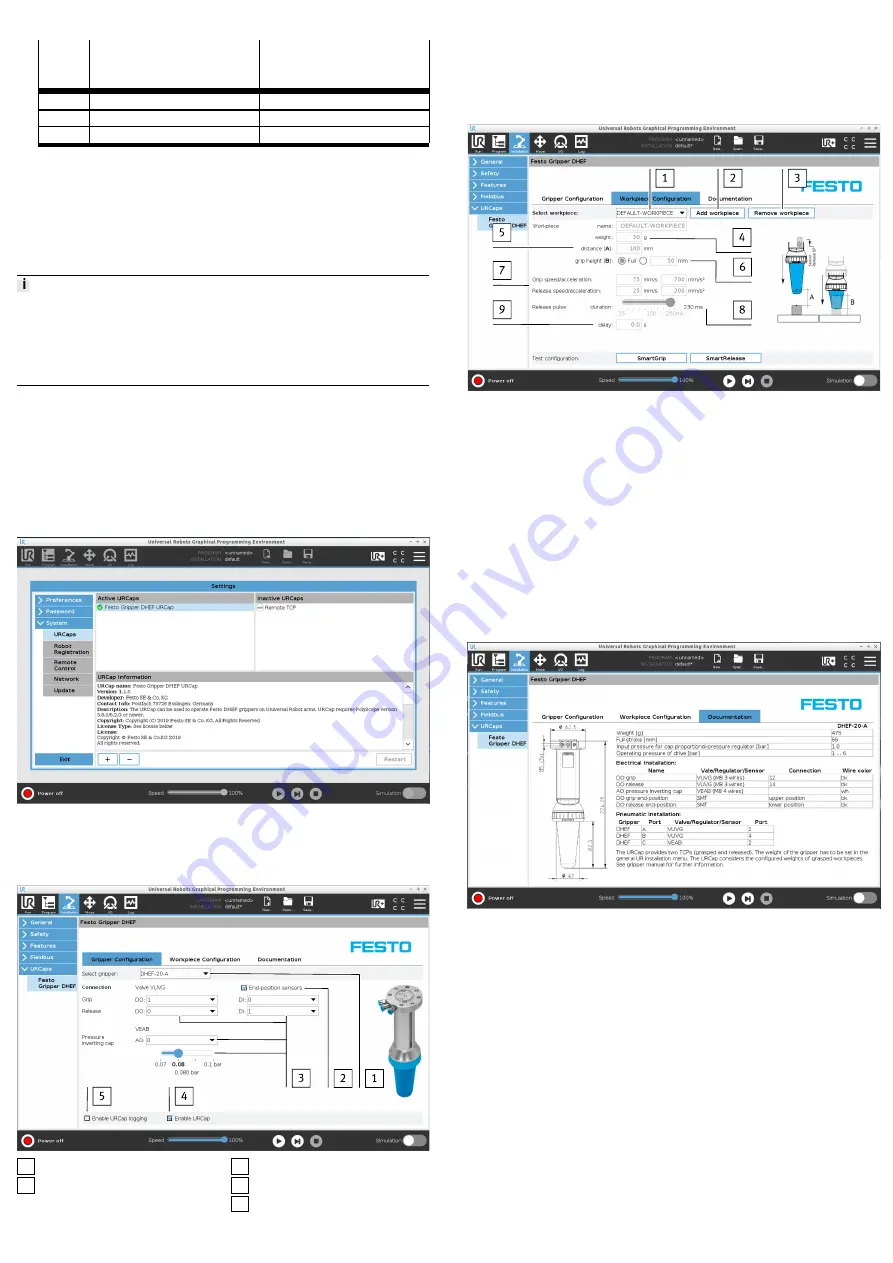
Workpiece configuration
Fig. 6 Workpiece configuration
1. Selection of stored workpieces
1
.
2. Create new workpieces in the list
2
or delete workpieces from the list
3
.
3. Input workpiece weight
4
.
4. Maximum distance between gripper and workpiece contact
5
.
5. Passive path of the gripper
6
.
6. Default values for speed and acceleration of the robot arm
7
.
7. Pressurisation time for advancing the piston rod
8
.
8. Deceleration of the pressurisation pulse after the start of the upward move-
ment
9
.
9. The preset values can be tested by the "SmartGrip" and "SmartRelease"
functions. The user is guided through the function via dialogue.
Documentation
Information on installing the software and technical data of the adaptive shape
gripper.
Fig. 7 Documentation
Toolbar for manual control of the adaptive shape gripper
The functions of the adaptive shape gripper can be tested manually after pneu-
matic and electrical installation. A program sequence is not necessary.