


6.2
Mounting intermediate position module on linear drive DGST
1. Fasten the intermediate-position module to the mounting surface underneath
with two screws and the accompanying centring sleeves . Tightening torque
Tab. 1 Tightening torque for mounting the intermediate position module.
The intermediate position is fine-tuned during commissioning by screwing the
cushioning component in or out.
7
2. Fasten the shock absorber retainer to the slide of the linear drive with four
screws . Tightening torque
Tab. 3 Tightening torque for mounting shock
absorber retainer on linear drive DGST.
6
DGST
-12
-16
-20
-25
Centring sleeve
Æ
5H7
Æ
12H7
Screw
M4
M5
M6
Tightening torque
[Nm]
2.9
5.2
8.4
Tab. 3: Tightening torque for mounting shock absorber retainer on linear drive
DGST
6.3
Required signal-to-noise ratio
Signal-to-noise ratio
When mounting the intermediate position module on the linear drive DGST, the
required signal-to-noise ratio must be observed
Fig. 2: Signal-to-noise ratio
DGST
-12
-16
-20
-25
Signal-to-noise ratio
[mm]
³
10
³
15
Tab. 4: Signal-to-noise ratio
7
Pneumatic installation
1. Connect pneumatic port 1 and pneumatic port 2 with tubing. Tightening
torque:
–
DADM-EP-G6-10: 0.5 Nm
–
DADM-EP-G6-16: 2 Nm
9
8
9
8
2. Seal unused ports with blanking plugs.
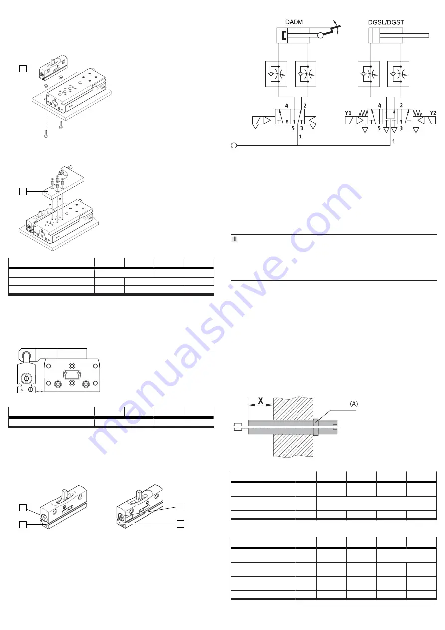
Possible control of a DADM in connection with DGSL/DGST
Fig. 3: Control of DADM with DGSL/DGST
8
Electrical installation
For sensing the stop lever positions:
1. Use suitable proximity switches with a longitudinal cable outlet
2. Place the proximity switches in the slots of the intermediate-position module.
3. Mount the proximity switches in the corresponding end position. A minimum
distance of 10 mm from magnetic parts must be observed.
9
Commissioning
Malfunctions may occur if excessive loads are applied to the stop lever.
• The following must be considered in this context:
• The stop lever must be retracted and advanced at the correct time.
• Briefly switch off pressure to the linear drive to retract the stop lever or
pressurise both sides.
1. Push the slide of the linear drive manually to the end position from which it is
to approach the intermediate position.
2. Pressurise the linear drive so the approached end position is retained.
3. Pressurise pneumatic port 1 on the intermediate-position module.
–
If required: the stop lever can be pressurised via the sliding pad . The
sliding pad serves as a manual override.
Ä
The stop lever extends.
4. Start a test run with low switching frequency and low impact speed. Linear
drive operating instructions
5. Slowly accelerate the payload on the linear drive. The slide of the linear drive
must not make a hard stop against the intermediate-position module.
6. If necessary: adjust the intermediate position by screwing in or unscrewing
the cushioning component on the shock absorber retainer . Maintain the
screw-on length X and the tightening torque A of the lock nut .
7. Terminate the test run.
Fig. 4: Screw-in length X and tightening torque A DADP-ES-G6/DADP-ES-G8
DADP-ES-G6
-10
-16
-20
-25
Screw-on length X with
DGSL-…-PA/-P1A/-Y3A
1)
[mm]
0 … 25.5
0 … 39.5
0 … 49.5
0 … 49
Screw-on length X with
DGSL-…-EA
1)
[mm]
0 … 5.5
Tightening torque A
[Nm]
3
5
8
20
1) Maximum adjustable end-position range
Tab. 5: Screw-on length X and tightening torque
DADP-ES-G8
-12
-16
-20
-25
Screw-on length X with
DGST-…-Y12A
1)
[mm]
0 … 13.6
0 … 15.7
0 … 20
Screw-on length X with
DGST-…-PA/P1A
1)
[mm]
0 … 19
0 … 21.5
0 … 25
0 … 35
Screw-on length X with
DGST-…-EA
1)
[mm]
0 … 7.6
0 … 9.85
0 … 5.5
0 … 2
Tightening torque
[Nm]
2
3
5
8
1) Maximum adjustable end-position range
Tab. 6: Screw-on length X and tightening torque


