The network-specific LED indicators are described later in the document
è
10 Diagnostics and fault clearance.
The system-specific LED indicators are described in “Instructions for use
ofsystem CPX-E” below
è
1.1 Further applicable documents.
5.4 Control components
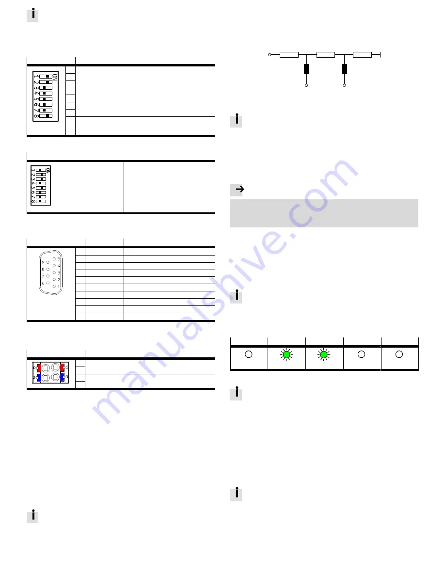
DIL switches
Function
1
The station number of the bus module is set binary coded using
DIL switches 1 ... 7 (permissible station numbers 1 ... 125).
Factory setting: 3
Example:
è
Fig. 7
2
3
4
5
6
7
8
Device-specific diagnostics
ON = Active (factory setting)
OFF = Inactive
Fig. 6
Example of setting the station number
DIL 1: OFF
2
0
=
1
Example:
DIL 2: ON
2
1
=
2
2
1
+ 2
2
+ 2
4
= 2 + 4 + 16 = 22
DIL 3: ON
2
2
=
4
DIL 4: OFF
2
3
=
8
è
Station number set = 22
DIL 5: ON
2
4
=
16
DIL 6: OFF
2
5
=
32
DIL 7: OFF
2
6
=
64
Fig. 7
5.5 Connecting components
Connection [XF1]
Signal
Designation
1
Shield
Functional earth
2
n.c.
–
3
RxD/TxD-P
Received/transmitted data P
4
CNTR-P
Repeater control signal
1)
5
DGND
Data reference potential (M5V)
6
VP
Supply voltage positive (P5V)
7
n.c.
–
8
RxD/TxD-N
Received/transmitted data N
9
n.c.
–
2)
Shield
Functional earth
1)
The repeater control signal CNTR-P is executed as a TTL signal.
2)
Housing
Fig. 8
Connection [XD]
1)
Signal
0
+24 V DC operating voltage supply U
EL/SEN
1
2
0 V DC operating voltage supply U
EL/SEN
3
1)
Ports XD.0 and XD.1 and ports XD.2 and XD.3, respectively, are connected to each other in the
terminalblock.
Fig. 9
Diagnostic interface [DIAG]
Via the diagnostic interface [DIAG] (mini-USB), the bus module can be connected
to a PC on which parameterisation and diagnostics software is installed.
6
Transport and storage
Observe specifications for the environmental and storage conditions
è
13 Technical data.
7
Mounting
The module is to be mounted in accordance with the “Instructions for use of
system CPX-E”
è
1.1 Further applicable documents.
8
Installation
8.1 Network
Use cables that meet the cable specification
è
Fig. 15.
You can find the corresponding connector plugs in the Festo catalogue
è
www.festo.com/catalogue.
Bus terminal with terminating resistors
If the bus module is at the start or end of a field bus segment, a bus terminal is
required.
Make sure that the bus terminal contains a resistor network having the following
configuration:
390
W
390
W
220
W
Pin 6
Pin 5
Pin 3
Pin 8
120 nH
120 nH
Fig. 10
Connection with fibre-optic cables (FOC)
The PROFIBUS-DP interface of the module corresponds to the
specification IEC 61158 and supports the control of network components
for fibre-optic cables.
8.2 Operating voltage supply U
EL/SEN
1. Make sure that the power supply is switched off.
2. Connect cables to the terminal block in accordance with the “Instructions for
use of system CPX-E”
è
1.1 Further applicable documents.
9
Commissioning
Note
Malfunction due to the higher-order controller and system CPX-E being switched
on in the incorrect order.
Switch on the higher-order controller and system CPX-E according to the
preset order of the network used.
1. Set up automation project for the higher-order controller with the help of the
corresponding software.
2. Load the device description file into the software
è
www.festo.com/sp.
3. Configure the system CPX-E in the software:
– System structure
– Network addressing
– I/O addressing
4. Transfer automation project to the higher-order controller.
Further information about commissioning the system CPX-E can be found
in the “Instructions for use of system CPX-E”. Information about the
parameters can be found in the “Description of system CPX-E” and in the
descriptions of the modules used
è
1.1 Further applicable documents.
Behaviour of display components following correct commissioning
[BF] (red)
[PS] (green)
[PL] (green)
[SF] (red)
[M] (yellow)
off
lights up
lights up
off
off
Fig. 11
Information about error elimination in the case of non-conforming
behaviour can be found in the “Description of system CPX-E” and in the
descriptions of the modules used
è
1.1 Further applicable documents.
10
Diagnostics and fault clearance
10.1 Diagnostics options
For the diagnostics of errors, various possibilities are available:
– Internal system diagnostics
– LED indicators on the product
10.2 Internal system diagnostics
Activate internal system diagnostics via the corresponding catalogue input.
– Status bits: CPX-E-PB DP slave [status]
– I/O diagnostic interface: CPX-E-PB DP slave [DP-V1]
The internal system diagnostics is described in the “Description of
systemCPX-E”
è
1.1 Further applicable documents.


