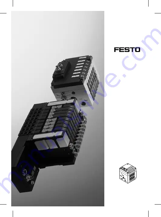
Brief description
CPV valve terminalwith AS-Interfacetype CPV..-GE-ASI-4-...
– English
8080210
2017-11e
[8080212]
Compact performance
Страница 1: ...Brief description CPV valve terminal with AS Interface type CPV GE ASI 4 English 8080210 2017 11e 8080212 Compact performance...
Страница 2: ...ciation Copyright Festo SE Co KG Ruiter Stra e 82 73734 Esslingen Germany Internet http www festo com E Mail service_international festo com Reproduction distribution or sale of this document or commu...
Страница 3: ...onnel especially trained for this purpose Detailed information on the design and method of addres sing your AS Interface bus system can be found in the man ual for your master Detailed information on...
Страница 4: ...connection 5 Type plate 6 Inscription field for AS Interface address As from hardware status HW 0105 see type plate Can be configured via DIP switch see sections 4 1 and 4 2 PWR LED Fault LED Meaning...
Страница 5: ...and outputs IO code 8H D0 D1 D2 D3 O O O O O0 O1 O2 O3 Outputs valve solenoid coils Data bits The address mapping depends on the configuration of the master 3 2 Assigning the AS Interface address Rec...
Страница 6: ...P switch settings see section 4 5 1 OFF 2 ON 3 OFF 4 ON 1 ON 2 OFF 3 ON 4 OFF 1 ON 2 OFF 3 OFF 4 ON J 3 Addresses of the solenoid coils for the AS Interface address 4 Addresses or LEDs of solenoid coi...
Страница 7: ...circuit on the valve solenoid coil wire fracture on the vale solenoid coil valve does not switch no movement of the plunger The diagnosis of the valve module can be deactivated via the AS Interface p...
Страница 8: ...tage supply via separate load voltage connection 1 Connect the additional supply with a cable socket type ASI SD FK to the load voltage connection Valves can be switched off during EMERGENCY STOP Conf...
Страница 9: ...uring the voltage supply on the bottom of the sub base 1 Setting DIP switch setting 1 With load voltage Supplying the valves via a separate load voltage connection additional supply 1 2 Off 3 4 On Wit...
Страница 10: ...rting the valve terminal S Switch on the power supply only if the DIP switch is positioned at a permitted setting Warning Use power supplies which guarantee reliable electrical isolation of the operat...
Страница 11: ...2 24 V brown 4 Pin 1 0 V blue 1 2 3 4 Can be configured via DIP switch see section 4 2 For connecting the valve terminal use the Festo cable sockets type ASI SD FK You will then comply with protection...
Страница 12: ...e section 4 2 1 2 3 4 5 Converting the valve terminal The valve terminal can be fitted with double solenoid and or single solenoid valves During conversion the new valve terminal configuration must be...
Страница 13: ...V Protection class as per EN 60529 Plug connector inserted or provided with protective cap IP65 Electromagnetic compatibility EMC interference emission EMC resistance to interference See declaration o...
Страница 14: ...e section 4 2 Rated value protected against incorrect polarity Residual ripple Max current consumption for 4 valves at 24 V a when switched on b after current reduction stationary 24 V DC 10 21 6 26 4...