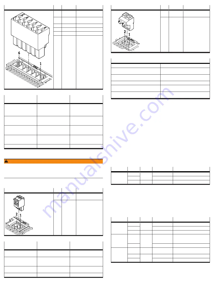
background image

[X9A]

Pin

Function

Description

6

DC+

DC link circuit positive
potential

5

DC-

DC link circuit negative
potential

4

L3

Mains supply phase L3

3

L2

Mains supply phase L2

2

L1

Mains supply phase L1

1

PE

Protective earthing

Tab. 37: Power supply and DC link circuit

Requirements for the
connecting cable

Single device

Device compound

Number of insulated wires and
shielding

4 insulated wires, unshielded

without DC link coupling:
4 wires, unshielded
with DC link coupling: 6 wires,
unshielded

Min. conductor cross section
including wire end sleeve with
plastic sleeve

0.5 mm

2

1.5 mm

2

Max. conductor cross section
including wire end sleeve with
plastic sleeve

4 mm

2

4 mm

2

Max. conductor cross section
including wire end sleeve
without plastic sleeve

6 mm

2

6 mm

2

Max. length

2 m

£

 0.5 m

Tab. 38: Requirements for the connecting cable

7.10.2

[X9C], logic voltage supply

WARNING

Risk of injury due to electric shock.
• For the electrical power supply with extra-low voltages, use only PELV circuits

that guarantee a reinforced isolation from the mains network.

• Observe IEC 60204-1/EN 60204-1.

Only connect PELV circuits with an output current of max. 25 A. Otherwise,
use a separate external fuse: 25 A.

[X9C]

Pin

Function

Description

2

24 V DC

positive potential of logic
voltage supply

1

0 V

Reference potential for
logic voltage supply

Tab. 39: Logic voltage supply

Requirements for the
connecting cable

Single device

Device compound

Number of insulated wires and
shielding

2 insulated wires, unshielded

2 insulated wires, unshielded

Min. conductor cross section
incl. wire end sleeve with
plastic sleeve

0.5 mm

2

0.5 mm

2

Max. conductor cross section
incl. plastic wire end sleeve

2.5 mm

2

2.5 mm

2

Max. length

2 m

0.5 m

Tab. 40: Requirements for the connecting cable

7.10.3

[X9B], connection for braking resistor

The connection [X9B] is located on the top of the device. The internal braking
resistor or a suitable external braking resistor is attached to the connection [X9B].

[X9B]

Pin

Function

Description

2

BR+Ch

Braking resistor positive
connection

1

BR-Ch

Braking resistor negative
connection

Tab. 41: Connection for the braking resistor

Requirements for the connecting cables of external braking resistors

Number of insulated wires and shielding

2 wires, shielded

Min. conductor cross section incl. wire end
sleeve with plastic sleeve

0.25 mm

2

Max. conductor cross section incl. plastic wire
end sleeve

2.5 mm

2

Max. cable length

2 m

Wiring

inside the control cabinet, shield connected to
PE

Tightening torque of the screw terminals on the
mating plug GIC 2.5 HCV/2-ST-7.62

0.5 … 0.6 Nm

1)

1) Specification of the manufacturer at the time the documentation was approved

Tab. 42: Requirements for the connecting cable
Selection of suitable braking resistors
Information on selecting suitable braking resistors 

è

 Manual Assembly, Installa-

tion.
7.11

Cross-wiring

Cross-wiring makes it possible to set up a device compound consisting of up to 10
servo drives CMMT-AS. The different cross-wiring options are as follows:

Cross-wiring of I/O signals at the connection [X1A]

Cross-wiring of the mains and logic voltage supply without DC link coupling

Cross-wiring of the mains and logic voltage supply with DC link coupling

Information on cross-wiring 

è

 Manual Assembly, Installation and Manual Safety

sub-function.
7.12

STO installation

Inputs and outputs for the safety sub-function STO
The 2-channel request for the safety sub-function is made via the digital inputs
#STO-A and #STO-B. The STA diagnostic output indicates whether the safe status
has been reached for the safety sub-function STO.

Connection Pin

Type

Identifier

Function

[X1A]

X1A.11

DIN

#STO-B

Safe torque off, channel B

X1A.12

#STO-A

Safe torque off, channel A

X1A.22

DOUT

STA

Safe torque off acknowledge

Tab. 43: Inputs and outputs for the safety sub-function STO

7.13

SBC installation

Inputs and outputs for the safety sub-function SBC
The 2-channel request for the safety sub-function is made via the digital inputs
#SBC-A and #SBC-B at the connection [X1A]. The SBA diagnostic output indicates
whether the safe status has been reached for the safety sub-function SBC. The
holding brake is connected via the connection [X6B]. The external clamping unit is
connected via the connection [X1C].

Connection Pin

Type

Identifier

Function

[X1A]

X1A.9

DIN

#SBC-B

Safe brake control, channel B

X1A.10

#SBC-A

Safe brake control, channel A

X1A.21

DOUT

SBA

Safe brake control acknowledge

[X1C]

X1C.1

DOUT

BR-EXT

Output for connection of an
external clamping unit (high-side
switch)

X1C.5

GND

Reference potential (ground)

[X6B]

X6B.1

FE

Functional earth connected to pro-
tective earth

X6B.2

OUT

BR+

Holding brake (positive potential)

X6B.3

BR–

Holding brake (negative potential)

Tab. 44: Inputs and outputs for the SBC safety sub-function

7.14

SS1 installation

Inputs and outputs for the safety sub-function SS1
The safety sub-function SS1 is wired like the safety sub-function STO but is
supplemented by the functional input CTRL-EN so that the braking ramp can be
activated by the safety relay unit.

Содержание CMMT-AS-C7/12-11A-P3-S1

Страница 1: ...and an 11 character alphanumeric code Festo SE Co KG Manufacturer DE 73734 Esslingen Manufacturer s address Made in Germany Country of origin Germany Tab 2 Product labelling example Warning symbols on the front of the product Warnin g symbol Meaning with the CMMT AS Attention Hot surface Metallic housing parts of the device can reach high temperatures during operation In the event of a fault inter...

Страница 2: ...hold the motor and axis in position at standstill The safety sub function SS1 is intended for performing a rapid stop with subse quent torque switch off 2 2 1 Application areas The device is intended for use in an industrial environment and with appropriate measures in commercial residential and mixed areas The device is intended for installation in a control cabinet The minimum degree of protecti...

Страница 3: ...24 V DC PELV 5 External braking resistor optional 6 Servo drive CMMT AS 7 Servo motor here EMME AS 8 PC with Ethernet connection for parameterisation 4 2 1 Overview of connection technology 1 2 3 4 5 6 7 8 9 10 11 12 13 14 15 16 Fig 2 Connections of the CMMT AS C7 C12 11A P3 example 1 PE connection housing 2 X9A Mains and DC link circuit connection 3 X9C Logic voltage 4 XF2 OUT RTE interface port ...

Страница 4: ...BC may only be used for holding brakes or clamping units which engage in the de energised state Ensure the lines are protected when installed SBC request The safety sub function SBC is requested on 2 channels by simultaneously switching off the control voltage at both control inputs SBC A and SBC B The SBC A request switches off the power to the signals BR BR The SBC B request switches off the pow...

Страница 5: ...ring For DC link coupling higher power devices must be placed closer to the mains supply If there is a voltage supply to the device when the control cabinet is open vertical access to the bottom and top of the device must be prevented For mounting on the rear wall of the control cabinet the servo drive cooling element has a slot on the top in the shape of a keyhole and an ordinary slot on the bott...

Страница 6: ...current of 3 5 mA or a DC current of 10 mA Always connect both protective earthing connections to the mains side PE connection the PE pin of X9A and PE earthing screw on the housing The minimum cross section of the protective earthing conductor must comply with the local safety regulations for protective earthing conductors for equipment with high leakage current 7 3 Mains fuse The CMMT AS does no...

Страница 7: ...t up and commissioning are performed by a professional with the neces sary experience for setting up and commissioning drive systems including their EMC aspects category C2 devices can be used in the first environment residential area For operation of category C2 devices limit values for the harmonic currents in the network EN 61000 3 2 or EN 61000 3 12 apply depending on the connected load of the...

Страница 8: ...Control input Safe torque off channel B 10 SBC A Control input Safe brake control channel A X1A Pin Function Description 9 SBC B Control input Safe brake control channel B 8 reserved do not connect 7 6 5 4 ERR RST Error acknowledgement 3 CTRL EN Power stage enable 2 AIN0 Differential analogue input 1 AIN0 Tab 16 Inputs and outputs for the higher order PLC with the CMMT AS S1 Requirements for the c...

Страница 9: ...der emulation Incremental encoder input Input of a slave axis for receiving the encoder signals of a master axis Tab 23 Possible functions of the connection X10 Requirements for the connecting cable Characteristics Encoder cable for servo drives shielded Optical shield cover 85 Separately twisted signal pairs recommended design 4 x 2 x 0 25 mm2 Max cable length 3 m Tab 24 Requirements for the conn...

Страница 10: ...mperature posi tive potential 4 FE Functional earth con nected to protective earth 3 BR Holding brake negative potential 2 BR Holding brake positive potential 1 FE Functional earth con nected to protective earth Tab 33 Motor auxiliary connection Requirements for the connecting cable Design 2 wires for the line to the holding brake twisted in pairs separately shielded 2 wires for the line to the te...

Страница 11: ...ase of block mounting the shield clamp makes full contact with the base of the housing cable diameter 12 mm Minimum tightening torque with larger cable diameter 12 mm 23 mm 0 5 Nm 15 With a higher tightening torque make sure the con necting cable does not get crushed in the clamping area due to excessive pressure Tab 36 Tightening torque and clamping range CMMT AS C7 C12 11A P3 1 2 3 4 5 Fig 11 Sh...

Страница 12: ...h 2 m Wiring inside the control cabinet shield connected to PE Tightening torque of the screw terminals on the mating plug GIC 2 5 HCV 2 ST 7 62 0 5 0 6 Nm1 1 Specification of the manufacturer at the time the documentation was approved Tab 42 Requirements for the connecting cable Selection of suitable braking resistors Information on selecting suitable braking resistors è Manual Assembly Installa ...

Страница 13: ...Establish the connection to the CMMT AS and set network configuration 5 Identify the technical data of the components that is required for configura tion 8 3 Commissioning steps NOTICE Unwanted drive movements or damage to components Incorrect parameterisation may result in unwanted drive movements or overload when the closed loop controller is enabled or may lead to connected components becoming ...

Страница 14: ... safety sub function has been requested Tab 49 Safety LED 11 2 Repair Repair or maintenance of the product is not permissible If necessary replace the complete product 1 If there is an internal defect Always replace the product 2 Send the defective product unchanged together with a description of the error and application back to Festo 3 Check with your regional Festo contact person to clarify the...

Страница 15: ...onformity The protection objectives of the Low Voltage Directive are fulfilled in accordance with the requirements of the EC Machinery Directive The requirements of the Low Voltage Directive are based on the product standard EN 61800 5 1 The valid version of the product standard is listed in the declaration of conformity General technical data Type ID code CMMT AS Type of mounting Mounting plate a...

Страница 16: ... power VRMS 380 Output frequency Hz 0 599 Duration for maximum current fs 5 Hz s 2 Duration for maximum current at standstill fs 5 Hz min imum cycle time 1 s s 0 1 Tab 63 Power specifications motor connection X6A 13 4 Technical data UL CSA certification In combination with the UL inspection mark on the product the information in this section must also be observed in order to comply with the certif...

Отзывы: