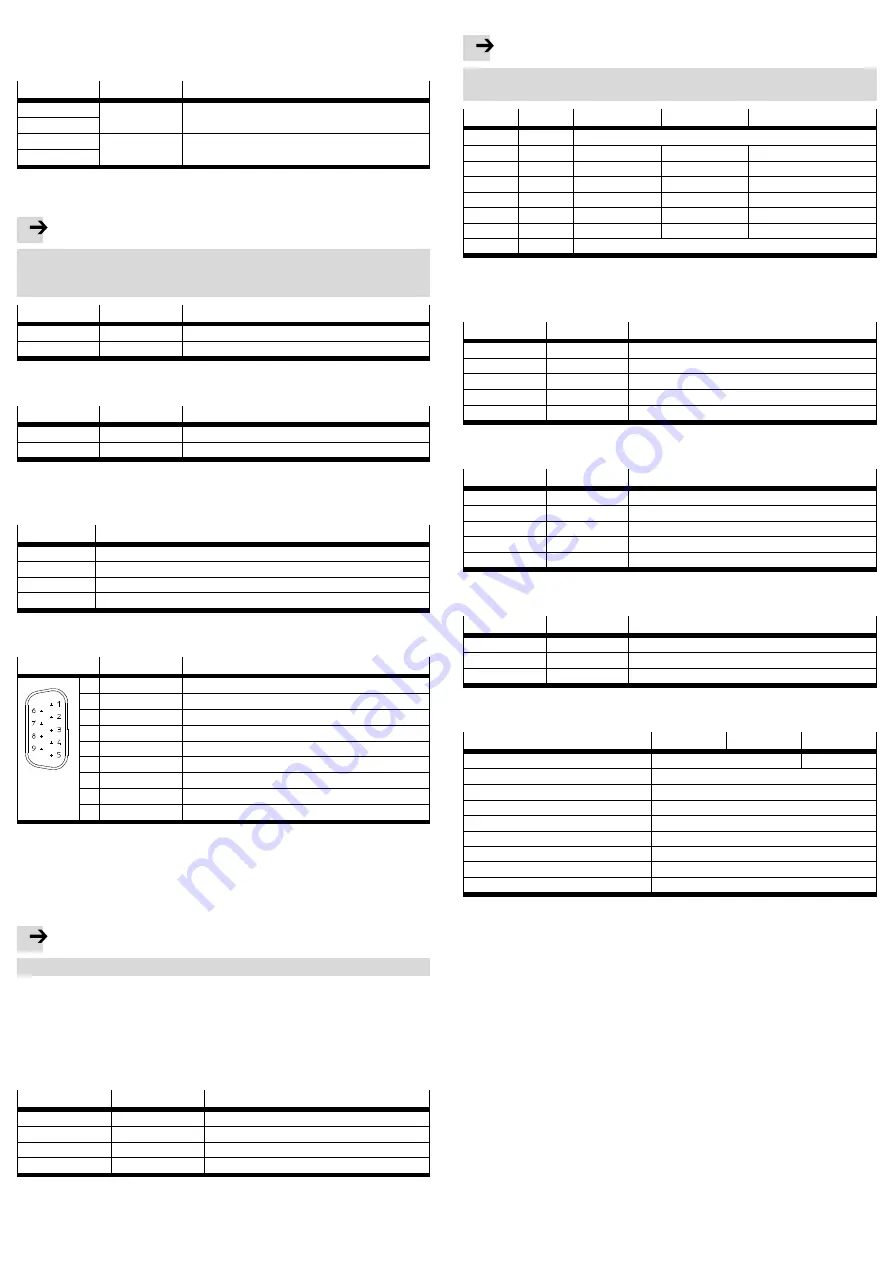
7.3 Load voltage supply infeed for IO-Link
This infeed is used for the power supply of IO-Link devices which are connected via
IO-Link master ports.
Connection to CECC-LK
Pin
Signal
Comment
X11.1
24
UA+ infeed for IO-Link master ports X12 … X15.4
X11.2
X11.3
0
UA- infeed for IO-Link master ports X12 … X15.5
X11.4
Fig. 6
Connection to CECC-S
Note
Damage to the device in the event of a mix-up of the connecting pins.
• When establishing the load voltage supply for the IO-Link master port on the
CECC-S, make sure that only connecting pins X11.1 and X11.2 are used.
Pin
Signal
Comment
X11.1
24
UA+ infeed for IO-Link master port X15.4
X11.2
0
UA- infeed for IO-Link master port X15.5
Fig. 7
7.4 Encoder power supply (CECC-S only)
Pin
Signal
Comment
X11.3
UG
Encoder power supply (ground)
X11.4
UE
Encoder power supply (5 V)
Fig. 8
8
Interfaces
8.1 I/O interface
Pin
Comment
X2.0 … X2.1
Fast digital inputs (180 kHz)
X2.2 … X2.7
Digital inputs (1 kHz)
X3.0 … X3.5
Digital inputs (1 kHz)
X4.0 … X4.7
Digital outputs
Fig. 9
8.2 CANopen interface X6
Pin
Signal
Comment
1
n.c.
not connected
2
CAN_L
1)
CAN-Bus- signal (dominant low)
3
CAN_GND
CAN Ground
4
n.c.
not connected
5
CAN_SHLD
Connection to functional earth
6
CAN_GND
CAN Ground (optional)
7
CAN_H
1)
CAN-Bus signal (dominant high)
8
n.c.
not connected
9
n.c.
not connected
1)
If the CECC is located at the end of the line, connect pin 2 and pin 7 using a terminating resistor.
A corresponding plug with terminal resistor (120 ohms/0.25 W) can be found in the
accessories
www.festo.com/catalogue.
Fig. 10
8.3 USB interface X7
The USB interface (Fig. 1
2
) is suitable for USB plug type A.
Note
• Only use storage media with a current consumption < 0.1 A.
8.4 Ethernet interface X8
The Ethernet interface (Fig. 1
1
) is designed as an RJ45 socket.
8.5 Serial interfaces (CECC-S only)
– X12 = RS232-1
– X13 = RS232-2
Pin
Signal
Comment
X12 … X13.1
G
Ground
X12 … X13.2
TX
Transmitted data
X12 … X13.3
RX
Received data
X12 … X13.4
S
Screening, connection to functional earth
Fig. 11
8.6 Multiple interface for encoder/RS422/RS485 (CECC-S only)
Note
The simultaneous use of all specified interfaces is not possible.
• Only use the signals from
one
interface.
Pin
Signal
Encoder
RS422
RS485
X14.1
G
Ground
X14.2
A+
Track A+
Transmitted data+
Transmitted/received data+
X14.3
A–
Track A–
Transmitted data–
Transmitted/received data–
X14.4
B+
Track B+
Received data+
n.c.
X14.5
B–
Track B–
Received data–
n.c.
X14.6
N+
Zero track+
n.c.
n.c.
X14.7
N–
Zero track–
n.c.
n.c.
X14.8
S
Screening, connection to functional earth
Fig. 12
8.7 Communication interface for IO-Link
4 x IO-Link master (CECC-LK only)
Pin
Signal
Comment
X12 … X15.1
L+
24 V
X12 … X15.2
C/Q
Communication signal IO-Link
X12 … X15.3
L–
0 V
X12 … X15.4
24
UA+
X12 … X15.5
0
UA–
Fig. 13
1 x IO-Link master (CECC-S only)
Pin
Signal
Comment
X15.1
L+
24 V
X15.2
C/Q
Communication signal IO-Link
X15.3
L–
0 V
X15.4
24
UA+
X15.5
0
UA–
Fig. 14
1 x IO-Link device (CECC-LK and CECC-S only)
Pin
Signal
Comment
X16.1
L+
24 V
X16.2
C/Q
Communication signal IO-Link
X16.3
L–
0V
Fig. 15
9
Technical data
CECC-...
LK
D
S
Operating voltage
VDC
19.2 … 30 VDC
20.4 … 30 VDC
Current consumption
ma
100 (nominal at 24 VDC)
Ambient temperature
°C
0 … 55
Storage temperature
°C
–25 … 70
Degree of protection
IP20
Protection class
III
Product weight
g
200
Certification
RCM
CE marking (
declaration of conformity)
in accordance with EU-EMV-RL
1),2)
1)
The device is intended for use in an industrial environment. Measures may need to be implemented in
residential areas for interference suppression.
2)
The device is classified in zone A in accordance with EN 61131-2:2007.
Fig. 16
Additional technical data can be found in the detailed description
www.festo.com/sp.


