© Festo Didactic 746310
29
•
Do not disconnect tubing while under pressure.
•
Danger of accident due to tubing slipping off!
– Use shortest possible tubing connections.
– Wear safety glasses.
Immediately deactivate compressed air supply if the tubing slips off.
•
Pneumatic circuit setup:
Connect the devices using plastic tubing with an outside diameter of 4 or 6 mm. Push the tubing into the
push-in connector as far as it will go.
•
Switch compressed air supply off before dismantling the circuit.
•
Dismantling pneumatic circuit:
Press the blue release ring down, after which the tubing can be pulled out.
5
Work instructions
Process engineering
•
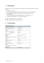
The lower tank may only be filled when supply power is switched off!
•
Switch 24 V DC power supply off and disconnect the power supply unit from 230 V DC power.
•
Use drinking water (recommended), which ensures long-term, maintenance-free operation of the
system.
•
The maximum permissible operating temperature of +65° C for the tank may not be exceeded.
•
The maximum permissible operating pressure of 0.5 bar for the liquid in the tubing may not be
exceeded.
•
The pump must not be allowed to run dry. The pump may not be used with seawater, contaminated
liquids or viscous media.
•
Empty the liquid from the system by opening the drain valve after completing experiments or before
changing the piping layout.
•
Inspect the liquid and replace it at least once a week if contaminated.
•
Clean the system as required, but in any case at least once a week. Do not use aggressive cleansers or
scouring agents.
•
The liquid ages if the system is left at a standstill for a lengthy period of time. Always empty the tanks
and the piping before leaving the system at a standstill for any length of time.
•
No liquids may be permitted to remain within the system for long periods of time, because this may
result in the growth of bacteria such as so-called legionellae.
Pneumatics
•
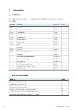
Set system pressure to a value within a range of 300 to 600 kPa (3 to 6 bar) for operation of the 2-way
ball valve with pneumatic quarter-turn actuator.
Содержание 746310
Страница 4: ...Festo Didactic 746310...
Страница 6: ...6 Festo Didactic 746310...
Страница 13: ...Festo Didactic 746310 13 Montageschritt 3 6 Oberer Tank...
Страница 20: ...20 Festo Didactic 746310 10 RI Flie bild EduKit PA Basic RI Flie bild EduKit PA Basic kompletter Aufbau...
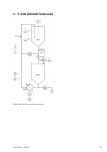
Страница 21: ...Festo Didactic 746310 21 11 RI Flie bild EduKit PA Advanced RI Flie bild EduKit PA Advanced kompletter Aufbau...
Страница 22: ...22 Festo Didactic 746310 12 Elektrischer Schaltplan EduKit PA Basic Schaltung mit Selbsthaltung...
Страница 26: ...26 Festo Didactic 746310...
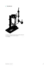
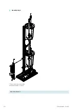
Страница 32: ...32 Festo Didactic 746310 Assembly step 2 4 Profile 20 x 40 x 180 mm 5 Pipes connectors manual valves...
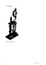
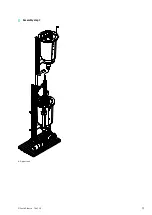
Страница 33: ...Festo Didactic 746310 33 Assembly step 3 6 Upper tank...
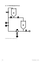
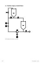
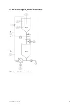
Страница 40: ...40 Festo Didactic 746310 10 P ID flow diagram EduKit PA Basic P ID flow diagram EduKit PA Basic complete setup...
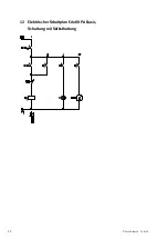
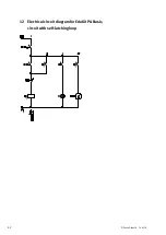
Страница 42: ...42 Festo Didactic 746310 12 Electrical circuit diagram for EduKit PA Basic circuit with self latching loop...
Страница 46: ...46 Festo Didactic 746310...
Страница 53: ...Festo Didactic 746310 53 Paso de montaje 3 6 Dep sito superior...
Страница 62: ...62 Festo Didactic 746310 12 Esquema de distribuci n el ctrico EduKit PA Basic circuito con autorretenci n...
Страница 66: ...66 Festo Didactic 746310...
Страница 72: ...72 Festo Didactic 746310 tape 2 4 Profil 20 mm x 40 mm x 180 mm 5 Tuyaux raccords et robinets manette...
Страница 73: ...Festo Didactic 746310 73 tape 3 6 Cuve sup rieure...
Страница 82: ...82 Festo Didactic 746310 12 Sch ma lectrique de l EduKit PA Basic montage automaintien...

