


42
Pegasus LN 2S
Cod. 3540G310 - 03/2007 (Rev. 02)
EN
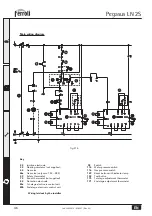
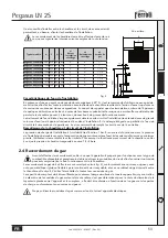
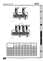
fig. 19
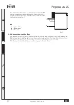
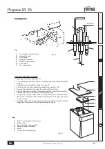
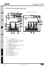
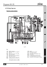
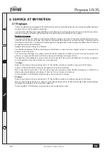
4.2 General view and main components
Key
1
“0 - 1 - TEST” switch
2
2-stage adjustment thermostat
3
2nd-stage electronic control unit reset button
4
1st-stage electronic control unit reset button
5
Thermometer water gauge
6
Plug
7
Safety
thermostat
8
Arrangement for fitting an electronic controller
9
Fume outlet on fume chamber
10
Water pressure switch
11
Automatic air vent valve
12
Gas pressure switch
13
Pilot burner together with electrodes
14
Gas
manifold
15
Pressure
point
16
Discharge
cock
17
Gas valve with 1st-stage ECU
17A
1st-stage gas valve
18
Gas valve with 2nd-stage ECU
18A
2nd stage gas valve
VERS. 119-136 (8-9 ELEM.)
VERS. 153-289 (10÷18 ELEM.)
15
15
13
14
16
17
11
9
8
7
5 4 6 3 2
1
10
12
18
13
17
17A
18
18A


