


Not for
Reproduction
42
6. Position the neutral lockout bolts to the center of the
notches of the neutral lockout plates.
7. Re-tighten the jam nuts.
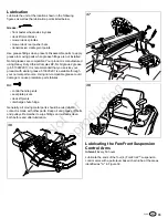
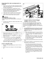
Parking Brake Adjustment
The parking brake mechanism consists of two parking brake
cables (A, Figure 56) that connect the parking brake lever
shaft to the parking brake control arm on the transmissions.
There is a parking brake spring on each parking brake cable
located below the engine deck by the transmission. The
position of the parking brake cable in the rear suspension
cradle is factory preset and should not be changed for parking
brake adjustment procedures. The adjustment is achieved by
changing the compressed spring length of the parking brake
springs.
56
1. Disengage the PTO, engage the parking brake, stop the
engine, and chock the tires.
2. Locate the parking brake springs (B) by the
transmissions.
3. With the parking brake engaged measure the
compressed spring length. The spring should measure
2-3/4" (7 cm) when compressed.
4. If the spring length does not equal the measurement, the
spring length will need to be adjusted.
5. Disengage the parking brake.
6. Loosen the set collar (C) and slide it away from the back
of the parking spring bracket (D).
CAUTION
Do not adjust the spring to be shorter than 2-1/2" (6.4
cm) when compressed. This may damage the brake
mechanism.
7. Turn the adjustment nut (E) to compress or release the
spring.
8. Engage the parking brake and re-measure the spring.
Continue this process until the compressed spring length
measures 2-3/4" (7 cm).
9. Position the set collar 3/8" (0,96 cm) away from the
parking brake bracket and tighten.
If this does not correct the braking problem, see your
authorized Ferris servicing dealer.
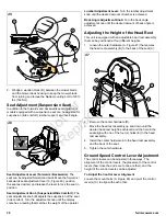
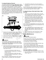
Deck Lift Rod Timing Adjustment
Checking the Deck Lift Rod Timing
1. Park the unit on a flat, level surface. Disengage the PTO,
engage the parking brake, turn the ignition switch to OFF.
Verify that the tires are inflated to the correct air pressure.
2. To check the inner lift rod (A, Figure 57) timing, measure
and record the distance between the inner lift pivots (B)
and the inner rod pivots (C). Repeat for the other side of
the unit.
57
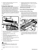
3. To check the outer lift rod timing (A, Figure 58), measure
and record the distance between the outer lift pivots (B)
and the outer rod pivots (C). Repeat for the other side of
the unit.
Содержание 5901572
Страница 1: ...N o t f o r R e p r o d u c t i o n ...
Страница 57: ...N o t f o r R e p r o d u c t i o n Notes ...
Страница 58: ...N o t f o r R e p r o d u c t i o n Notes ...
Страница 59: ...N o t f o r R e p r o d u c t i o n Notes ...
Страница 60: ...N o t f o r R e p r o d u c t i o n ...


