6
EN
ASSEMBLy
4
Before assembly, always switch off the
machine and remove the mains plug
from the mains.
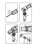
Mounting and removing the drill bit (fig. B)
The machine is suitable for use of the following
drill bits:
- Wood (HSS)
- Metal (HSS)
- Concrete / masonry (hard metal)
Mounting
● Open the chuck (6) by turning the collar (11)
counterclockwise.
● Insert the drill bit (12) into the chuck (6).
● Close the chuck (6) by turning the collar (11)
clockwise.
Removing
● Open the chuck (6) by turning the collar (11)
counterclockwise.
● Remove the drill bit (12) from the chuck (6).
● Close the chuck (6) by turning the collar (11)
clockwise.
Mounting and removing the auxiliary grip (fig. C)
Mounting
● Loosen the auxiliary grip (8).
● Slide the auxiliary grip (8) over the chuck (6).
● Turn the auxiliary grip (8) to the required
position.
● Tighten the auxiliary grip (8).
Removing
● Loosen the auxiliary grip (8).
● Remove the auxiliary grip (8) from the chuck (6).
● Tighten the auxiliary grip (8).
Mounting and removing the depth stop (fig. D)
The depth stop is used to set the maximum
drilling depth.
Mounting
● Loosen the auxiliary grip (8).
● Insert the depth stop (9) through the hole in
the auxiliary grip (8).
● Set the depth stop (9) to the required position.
● Tighten the auxiliary grip (8).
Removing
● Loosen the auxiliary grip (8).
● Remove the depth stop (9) from the auxiliary
grip (8).
● Tighten the auxiliary grip (8).
USE
Switching on and off (fig. A)
● To switch on the machine, press the on/off
switch (1). The further the on/off switch (1) is
pressed, the higher the speed of the machine.
● To switch the machine to continuous mode,
keep the on/off switch (1) pressed and
simultaneously press the lock-on button (2).
● To switch off continuous mode, press the
on/off switch (1) again.
● To switch off the machine, release the on/off
switch (1).
forward/reverse switch (fig. A)
2
Do not change the direction of rotation
during use.
● For clockwise rotation, slide the forward/
reverse switch (4) to the left.
● For counterclockwise rotation, slide the
forward/reverse switch (4) to the right.
Setting the maximum drilling speed (fig. A)
2
Do not set the speed during use.
● Turn the speed adjustment wheel (3) clockwise
to increase the maximum drilling speed.
● Turn the speed adjustment wheel (3)
counterclockwise to decrease the maximum
drilling speed.
Setting the operating mode (fig. E)
2
Do not change the operating mode
during use.
● Set the switch (5) to position „A“ for drilling.
● Set the switch (5) to position „B“ for hammer
drilling.
Hints for optimum use
● Clamp the workpiece.
● Firmly hold the machine with both hands.
● Place the drill bit on the workpiece.
● Switch on the machine.
● Do not apply too much pressure on the
machine. Let the machine do the work.
● Switch off the machine and wait for the
machine to come to a complete standstill
before putting the machine down.
Содержание PDM1027
Страница 2: ...2 1 5 6 4 3 9 7 8 10 A...
Страница 3: ...8 6 6 11 12 C B 8 9 F D E 5 11 12 14 8 13...
Страница 84: ...84 RU 5 A I D 7 8 9 3 1 5 2...
Страница 86: ...86 RU 8 8 8 8 6 8 D 8 9 8 9 8 8 9 8 8 A 1 1 1 2 1 1 2 4 4 2 3 3 2 5 5 4...
Страница 87: ...87 UA 12 12 F 13 14 8 12 10 14 8 8 2002 96 PDM1027 Ferm Ferm 1 1 2 3 4 5...
Страница 88: ...88 UA A I D 7 8 9 3 1 5 2 PDM1027 230 50 710 1 0 2 700 1 0 43 200 25 13 10 IP 20 1 9...
Страница 90: ...90 UA 8 9 8 9 8 8 9 8 8 1 1 1 2 1 1 2 4 4 2 3 3 E 2 5 A 5 B 4 12 12...
Страница 91: ...91 EL F 13 14 8 12 10 14 8 8 2002 96 EC PDM1027 Ferm Ferm 1 1 2 3 4 5 A...
Страница 92: ...92 EL I D 7 8 9 3 1 5 mm2 PDM1027 V 230 Hz 50 W 710 min 1 0 2 700 min 1 0 43 200 mm 25 mm 13 mm 10 IP 20 kg 1 9...
Страница 94: ...94 EL 8 9 8 8 1 1 1 2 1 1 A 2 4 4 A 2 3 3 2 5 A 5 B 4 12 12 F 13 14 8 12 10...
Страница 95: ...95 BG 14 8 8 2002 96 E PDM1027 Ferm Ferm 1 1 2 3 4 5...
Страница 98: ...98 BG 8 9 8 9 8 8 9 8 8 A 1 1 1 2 1 1 A 2 4 4 2 3 3 E 2 5 A 5 4 12 12...
Страница 99: ...99 BG F 13 14 8 12 10 14 8 8 2002 96 E...
Страница 101: ...101...
Страница 102: ...102...
Страница 104: ...www ferm com 1309 13...

