


EPC1200 SERIES OPERATION MANUAL
16/58
4.4.3- Parallel interface pins assignment for each mode
Pin
Source
Compatibility mode
Nibble mode
1 Host
Sys.
nStrobe
HostClk
2
Host Sys/printer Data0 (LSB)
Data0 (LSB)
3 Host
Sys/printer Data1
Data1
4 Host
Sys/printer Data2
Data2
5 Host
Sys/printer Data3
Data3
6 Host
Sys/printer Data4
Data4
7 Host
Sys/printer Data5
Data5
8 Host
Sys/printer Data6
Data6
9
Printer
Data7 (MSB)
Data7 (MSB)
10 Printer
nAck
PrtClk
11 Printer
Busy
PrtBusy/Data3,7
12 Printer
PError
AckDataReq/Data2,6
13 Printer
Selected
Xflag/Data1,5
14 Host
Sys.
Nautofeed
HostBusy
15 Printer
nFault
nDataAvail/Data0,4
16 Host
Sys.
nInit
NInit
17 Host
Sys.
nSelectIn
1284-Active
18-25
GND
GND
Table 3. -
PC parallel connector (DB25)
NOTES:
1) The ‘n’ prefix used before a signal name means that they are active in ‘0’ logic level. If the host
system does not provide any of the signal lines mentioned above, both communication types
could fail.
2) It is recommended to use twisted pair cables (signal/ground), with the return sides connected to
the system signal ground level.
3) Do not ignore the nACK and BUSY signals during data transmissions. An attempt to transmit
data without nACK or BUSY control signals might cause lost data.
4) The interface cables should have the minimum required possible length (maximum
recommended length: 2 m).
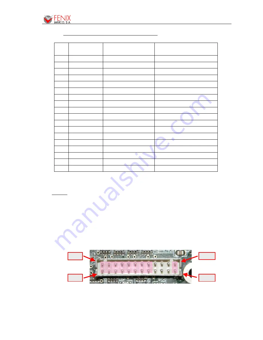
Fig. 11. -
Parallel interface pins
Pin #1
Pin #2
Pin #23
Pin #24


