background image

4

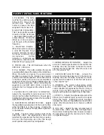
A. EFFECTS 

- This knob controls

the amount of signal its respective
channel sends to the overall effects
mix.  When the knob is set at 0, the
output is “dry”.   

B. HIGH

-  Adjusts the amount of

high frequency boost or cut in the
channel.  When all the tone controls
are set at 0 (straight up), the
channel is “flat” with no frequencies
cut or boosted.

C. MID 

- Adjusts the amount of

middle frequency boost or cut in
the  channel.

D. LOW

-  Adjusts the amount of

low frequency boost or cut in the
channel.

E. MONITOR

- This knob controls

the amount of signal its respective
channel sends to the monitor mix.
When the knob is set at 0, the
channel’s signal is not sent to the
monitor bus.

F. LEVEL - 

Adjusts the volume

control of the individual channel.
Rotating the knob clockwise
increases the respective channel’s
contribution to the “Main Out” mix.
Adjust this control after the MAIN or
overall volume of the SRM 6302 /
8302 has been set.  

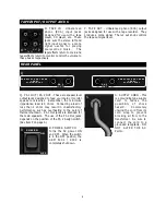
G. LINE - 

Plug your instrument in

here.  This 1/4 inch TRS balanced
input jack suited for use with items
having a line level output such as
high impedance microphones,
keyboards, drum machines,
outboard effects, etc.  It accepts
both balanced and unbalanced
cables

H. MIC

- Plug your microphone in

here.  This three pin XLR balanced
female input connector is intended
for input signals from low

impedance microphones.  Pins 2 and 3 provide
Phantom Power (+48V DC) for condenser style
microphones when the phantom power switch is on.

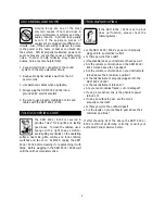
I. MAIN OUT 

- This 1/4 inch, TS, unbalanced, line

level output is designed to feed the SRM 6302  /
8302’s main bus signal to an external power
amplifier or main house mixer.     

J. PA 1 IN 

-  This 1/4 inch, TS, unbalanced, line

level input jack allows the SRM 6302 / 8302’s power
amplifier #1 (PA 1) to be fed from an external signal
source.  When this connection is used, the “main
out” connection to PA 1 is overridden.

K. MON OUT 

- This 1/4 inch, TS, unbalanced, line

level output is designed to feed the SRM 6302  /
8302’s monitor bus signal to an external power
amplifier or monitor system.

L. PA 2 IN 

-  This 1/4 inch, TS, unbalanced, line

level input jack allows the SRM 6302 / 8302’s power
amplifier #2 (PA 2) to be fed from an external signal
source.  When this connection is used, the internal
connection to PA 2 is overridden.

M. EFFECTS OUT/FOOTSWITCH 

- This 1/4 inch,

TS, unbalanced, line level output jack is designed to
feed the SRM’s effects bus signal to an external
signal processing device, such as a digital delay or a
chorus unit.  When a footswitch (P/N 048458,
optional) is inserted into this jack, the SRM’s internal
reverb can be turned on or off remotely. 

N. EFFECTS IN - 

This 1/4 inch, unbalanced, TS, line

level input jack is designed to accept signal from an
external processing device, such as a digital delay or
a chorus unit.  The signal entering this jack is mixed
into the Main and Monitor using the “Tape/Effects”
controls labeled “

Return to Main” 

and 

“Return  to

Monitor”

0

MAX

LEVEL

MONITOR

LOW

MID

HIGH

0

MAX

EFFECTS

LOW

MID

HIGH

0

MAX

+15


15

+15


15

+15


15

INPUT CHANNEL CONTROL FUNCTIONS

A

B

D

C

E

F

MAIN OUT

PA 1 IN

MON OUT

EFFECTS OUT/

FOOTSWITCH

PA 2 IN

EFFECTS IN

K

M

I

J

L

N

INPUT CHANNEL CONNECTIONS

LINE

MIC

G

H

PATCH BAY PANEL CONNECTIONS

Содержание SRM 6302

Страница 1: ...6 3 0 2 8 3 0 2 6 3 0 2 8 3 0 2 Owner s Manual for SRM 6302 8302 P N 050804 REV A From Fender Pro Audio POWERED MIXERS...

Страница 2: ...be treated with special care and attention to detail At Fender we know what building quality musical instruments and sound reinforcement equipment is all about In fact many of the world s best soundi...

Страница 3: ...input jacks and stereo RCA input jacks your SRM 6302 8302 can accommodate almost any input connection and signal level Ideal for live music churches auditoriums hotel conference or meeting rooms your...

Страница 4: ...level output is designed to feed the SRM 6302 8302 s main bus signal to an external power amplifier or main house mixer J PA 1 IN This 1 4 inch TS unbalanced line level input jack allows the SRM 6302...

Страница 5: ...nal sent to the main mix H MAIN The main output volume control of the SRM 6302 8302 Any adjustments to this control will affect the signal level at the Main Out as well as PA1 and PA2 depending upon t...

Страница 6: ...Connecting a load of less than 4 ohms may result in unsatisfactory performance such as overheating to the point of thermal shutdown PA 1 Out jacks are intended for the main speakers The use of the PA...

Страница 7: ...ility of the entire sound system If long speaker cables are required it is important to ensure the cable is sufficient to transfer all of the available amplifier power to the speakers rather than abso...

Страница 8: ...ment ON then the SRM 6302 8302 8 Increase volume controls and effects level controls to their desired levels listening for feedback or ringing 9 When shutting down the SRM 6302 8302 turn OFF the SRM 6...

Страница 9: ...on the operating surface heat sink grille volume and tone controls switches and line cord ALWAYS unplug the SRM 6302 8302 before cleaning it or approaching it with fluids Before plugging in the SRM 6...

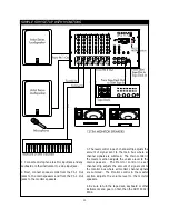
Страница 10: ...djusts the amount of signal sent to the main bus where all channel signals are summed The Main control in the master section adjusts the volume level to the main speakers The Monitor control in each c...

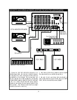
Страница 11: ...e SRM When PA 2 is assigned to the main front of house enclosures be sure one enclosure is connected to a PA 1 Out jack and the other is connected to a PA 2 Out jack 3 The Effects control in each chan...

Страница 12: ...main bus for additional power to the front of house speakers When PA 2 is assigned to the main front of house enclosures be sure one enclosure is connected to the PA 1 Out jacks and the other is conne...

Страница 13: ...r speakers by connecting a small shielded jumper cable from the Mon Out jack to PA 1 In Next connect the PA2 power amp to Monitor Out by placing the PA2 Assign switch to the Mon position The Monitor c...

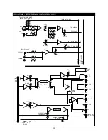
Страница 14: ...R EFFECTS REVERB MAIN PHANTOM EFFECTS IN L MONITOR EFFECTS REVERB MAIN PHANTOM PHANTOM POWER SWITCH 48 VDC REVERB DELAY LINE REVERB RETURN TO MONITOR EFFECTS REVERB RETURN TO MAIN MAIN GRAPHIC EQ MONI...

Страница 15: ...15 dB 30 Hz Mid 15 dB 750 Hz High 15 dB 15 kHz GRAPHIC EQUALIZER 12 dB 63 125 250 500 1 k 2 k 4 k 8 k and 16 kHz OVERALL AMPLIFIER 3 dB 10 Hz to 3 dB 50 kHz FREQUENCY RESPONSE Line In 10 mV PHANTOM PO...

Страница 16: ...5 mV CHANNEL TONE CONTROLS Low 15 dB 30 Hz Mid 15 dB 750 Hz High 15 dB 15 kHz GRAPHIC EQUALIZER 12 dB 63 125 250 500 1 k 2 k 4 k 8 k and 16 kHz OVERALL AMPLIFIER 3 dB 10 Hz to 3 dB 50 kHz FREQUENCY RE...

Отзывы: