Fema Smart DCM Скачать руководство пользователя страница 12

SMART DCM SWITCH / SN TRANSMITTER – OPERATING INSTRUCTIONS 


Manufactured for and on behalf of the Environmental and Combustion Controls Division of Honeywell Technologies Sàrl, Ecublens, Route du Bois 37, Switzerland by its Authorized Representative:


Fema Controls 
Honeywell GmbH 

P.O. Box 1254 
D-71099 Schönaich 
phone: (49) 7031-637-02 
fax:     (49) 7031-637-850 
http:/honeywell.de/fema 
 
Subject to change without notice. Printed in Germany 
 
MU0B-0560GE51 R0207A 
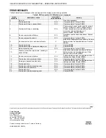
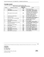
ERROR MESSAGES 

Table 8 lists all error messages which can appear in the display screen during operation. 

Table 8. SN Transmitter / DCM Switch error messages 

screen 

contents 

description / cause 

recoverable / 

unrecoverable 

remedy 

No error. 

-- 

No action necessary. 

Electronics failure. 

R/U 

If unrecoverable: Contact FEMA. 

Electronics failure or sensor failure. 

R/U 

If unrecoverable: Contact FEMA. 

Electronics failure or miswiring. 

R/U 

Check wiring (current meter used for current 
output? Voltmeter used for voltage output?). 
Correct detected errors and perform a hard-
ware reset as described above. If 
unrecoverable: Contact FEMA. 

Device memory check failure. 

R/U 

Hardware reset as described above. Contact 
FEMA. 

Device program flow failure. 

R/U 

If unrecoverable: Contact FEMA. 

Environment too hot or electronics failure. 

Eliminate overtemperature conditions. Perform 
hardware reset as described above. Contact 
FEMA. 

10 

Electronics failure. 

Contact FEMA. 

11 

Electronics failure or data processing error. 

Contact FEMA. 

12 

Data processing error. 

R/U 

If unrecoverable: Contact FEMA. 

13 

Pressure exceeds overpressure, resulting in 
sensor failure. 

Eliminate overpressure conditions. Perform 
hardware reset as described above. If this 
does not help: Contact FEMA. 

15 

Device memory check failure. 

R/U 

Perform hardware reset as described above. If 
this does not help: Contact FEMA. 

16 

Electronics (microcontroller) failure. 

R/U 

If unrecoverable: Contact FEMA. 

17 

Damage to application state data. 

R/U 

Perform hardware reset as described above. If 
this does not help: Contact FEMA. 

18 

Electronics error. 

R/U 

If unrecoverable: Contact FEMA. 

19 

Electronics or data processing error. 

R/U 

If unrecoverable: Contact FEMA. 

20 

Electronics or sensor error. 

R/U 

If unrecoverable: Contact FEMA. 

21 

Electronics error. 

R/U 

If unrecoverable: Contact FEMA. 

22 

Electronics or data processing error. 

Contact FEMA. 


Содержание Smart DCM

Страница 1: ...0 95 r h non condensing Temperature of medium 30 100 C 16 bar models 40 100 C 16 bar models Storage temperature Versions non HMI 40 80 C 16 bar 40 100 C 16 bar Versions HMI 30 80 C Climate class Indo...

Страница 2: ...here the device will check the plausibility of your values and if necessary redirect you back to the PARAMETRIZATION LEVEL and The CONFIRMATION LEVEL where you can review your edited values before per...

Страница 3: ...to local ambient atmospheric pressure and to compensate for drift To use this function properly the device must be mounted in the application and the pressure sensor exposed to local ambient atmosphe...

Страница 4: ...e simulation mode is started No The device remains in its normal operating mode The default setting is No WARNING After you have completed testing in the simulation mode do not forget to return to thi...

Страница 5: ...250 mA the load is disconnected and the WARN output is set to 0 5 V in a loop Table 2 DCM Switch functions and definitions definition function equa tion active inactive max monitor N O 1 closed open m...

Страница 6: ...ausibility of your values and if necessary redirect you back to the PARAMETRIZATION LEVEL and The CONFIRMATION LEVEL where you can review your edited values before permanently storing them START SCREE...

Страница 7: ...2 Wire Trans mitter is 4 20 mA However it can be inverted to 20 4 mA see section Function below FUNCTION Here you can invert the device s function see also Fig 15 Non invert the mode current range or...

Страница 8: ...e contrast is increased to its maximum value The default setting is Mean EXTRAS SIMUL SIMULATION MODE The simulation mode allows the user to test the device within the application without actually app...

Страница 9: ...passive 0 mA 3 Wire 0 10 V passive 0 V The output limits of the device s outputs at overpressure and underpressure are as follows Table 4 SN Transmitter output limits at over underpressure device out...

Страница 10: ...er The Y axis displays the generated output in the range according to the output definition see Fig 15 on page 7 and Table 5 on page 9 DCM SWITCH Measuring pressures is the safety function of the dire...

Страница 11: ...output pin 2 If due to miswiring or electronic failure the signal output cannot reach the desired high failure state it will auto matically go to the low failure state Table 6 SN Transmitter error rep...

Страница 12: ...ontact FEMA 6 Device memory check failure R U Hardware reset as described above Contact FEMA 7 Device program flow failure R U If unrecoverable Contact FEMA 8 Environment too hot or electronics failur...

Страница 13: ...sionen mit HMI 20 70 C Rel Luftfeuchtigkeit 0 95 nicht kondensierend Mediumtemperatur 30 100 C 16 bar Modelle 40 100 C 16 bar Modelle Lagertemperatur Versionen ohne HMI 40 80 C 16 bar 40 100 C 16 bar...

Страница 14: ...ener Einstellwerte PR FBEREICH berpr fung auf korrekte Eingabe und ggfls Zur ckstufung in den PARAMETRISIERUNGS BEREICH und BEST TIGUNGSBEREICH Nochmalige Best tigung der Einstellwerte bevor sie dauer...

Страница 15: ...st N O AUTO ZERO Die auto zero Funktion erm glicht es dem Anwender das Ger t entsprechend den lokalen atmosph rischen Druck verh ltnissen einzustellen sowie die Drift auszugleichen Um diese Funktion r...

Страница 16: ...das Ger t wieder in Sicherheitsanwendungen eingesetzt werden Yes Der Simulationsmodus wird aufgerufen No Das Ger t bleibt in seiner normalen Betriebsart Die Werkseinstellung ist No VORSICHT Nach Absc...

Страница 17: ...annungsversorgung gestellt Falls der Strom immer noch h her als 250 mA ist wird die Last getrennt und der WARN Ausgang auf 0 5 V in eine Schleife gestellt Tabelle 2 DCM Funktionen und Definitionen Def...

Страница 18: ...ung auf korrekte Eingabe und ggfls Zur ckstufung in den PARAMETRISIERUNGS BEREICH und BEST TIGUNGSBEREICH Nochmalige Best tigung der Einstellwerte bevor sie dauerhaft gespeichert werden STARTANZEIGE B...

Страница 19: ...tiert werden siehe Abschnitt Function Funktion unten FUNCTION FUNKTION Hier k nnen Sie die Ger tefunktion invertieren siehe auch Abb 15 Non invert der Modus Strom bzw Spannungsbereich wird auf 0 4 20...

Страница 20: ...Simulationsmodus erm glicht es dem Anwender die reibungslose Funktion des Ger ts zu pr fen ohne das System unter Druck zu setzen Nach Aufrufen des Simulationsmodus sind die Diagnostik funktionen nicht...

Страница 21: ...V passiv 0 V Die Ausgangsgrenzen der Ger teausg nge bei ber und Unterdruck sind wie folgt Tabelle 4 SN Transmitter Ausgangsgrenzen bei ber und Unterdruck Ger t Ausgangs signal bereich min Ausgangs gre...

Страница 22: ...te besteht darin Dr cke zu messen Je nach dem wie das Ger t eingestellt ist l t es sich mit einer Genauigkeit von 5 als Max Min oder Window W chter Schalter ausgang und WARN Ausgang betreiben Wenn di...

Страница 23: ...er automatisch in den niedrigen Fehlerzustand fallen Tabelle 6 SN Transmitter Fehlermeldung Fehlermeldung Modell Aus gangs signal Bereich prim rer hoher Fehler zustand sekund rer niedriger Fehler zust...

Страница 24: ...ntaktieren 6 Speicherpr fung fehlgeschlagen B NB Wie oben beschrieben Hardware Reset durchf hren FEMA kontaktieren 7 Programmlauffehler B NB Falls nichtbehebbar FEMA kontaktieren 8 Umgebung zu hei ode...

Отзывы: