


· MANUFACTURING FOR INDUSTRIAL AUTOMATION
8
10.3. ‘Tools’ menu
HOW TO ACCESS THE ‘TOOLS’ MENU
With the instrument in ‘
normal mode
’ of operation (see section 10.1),
press for 1 second the ‘
UP
’ (
5
) key. The horizontal leds light from
bottom to top. When the upper led lights, the instrument activates the
‘
tools
’ menu.
If the key is released before activating the ‘
tools
’ menu, the
horizontal leds light downwards from top to bottom, and the
instrument returns to ‘
normal mode
’ of operation.
Inside the ‘
tools
’ menu, the decimal point is not active.
Inside the ‘
tools
’ menu, the ‘
configuration digits
’ indicate the first function
available.
• press the ‘
UP
’ (
5
) key to move to the next function.
• press the ‘
SQ
’ (
<
) key to activate the selected function.
To exit the ‘
tools
’ menu, press the ‘
UP
’ (
5
) key until the parameter ‘
--
’
appears, and press the ‘
SQ
’ (
<
) key (or wait 60 seconds without pressing
any key to wait for the automatic ‘
rollback
’).
When exiting the ‘
tools
’ menu, the horizontal leds light down
from top to bottom, and the instrument returns to ‘normal
mode’ of operation.
‘ROLLBACK’ FUNCTION
If there is no interaction from the operator for 60 seconds, the instrument
exits the ‘
tools
’ menu and returns to ‘normal mode’ of operation.
AVAILABLE FUNCTIONS
The ‘
Force low
’ (
FL
) and ‘
Force high
’ (
Fh
) functions allow to temporarily
force the output signals to the low and high levels of the actual output
signal ranges selected. These tools allow to easily validate the correct
function of the remote elements connected to the instrument outputs.
• select ‘
Force low
’ (
FL
) function to set both output signals to the
minimum value of the selected ranges (4 mA). The ‘
FL
’ flash message
indicates that the function is active. Press any key to deactivate and
return to the ‘
Force low
’ (
FL
) menu entry.
• select ‘
Force high
’ (
Fh
) function to set both output signal to the
maximum value of the selected range (20 mA). The ‘
Fh
’ flash message
indicates that the function is active. Press any key to deactivate and
return to the ‘
Force high
’ (
Fh
) menu entry.
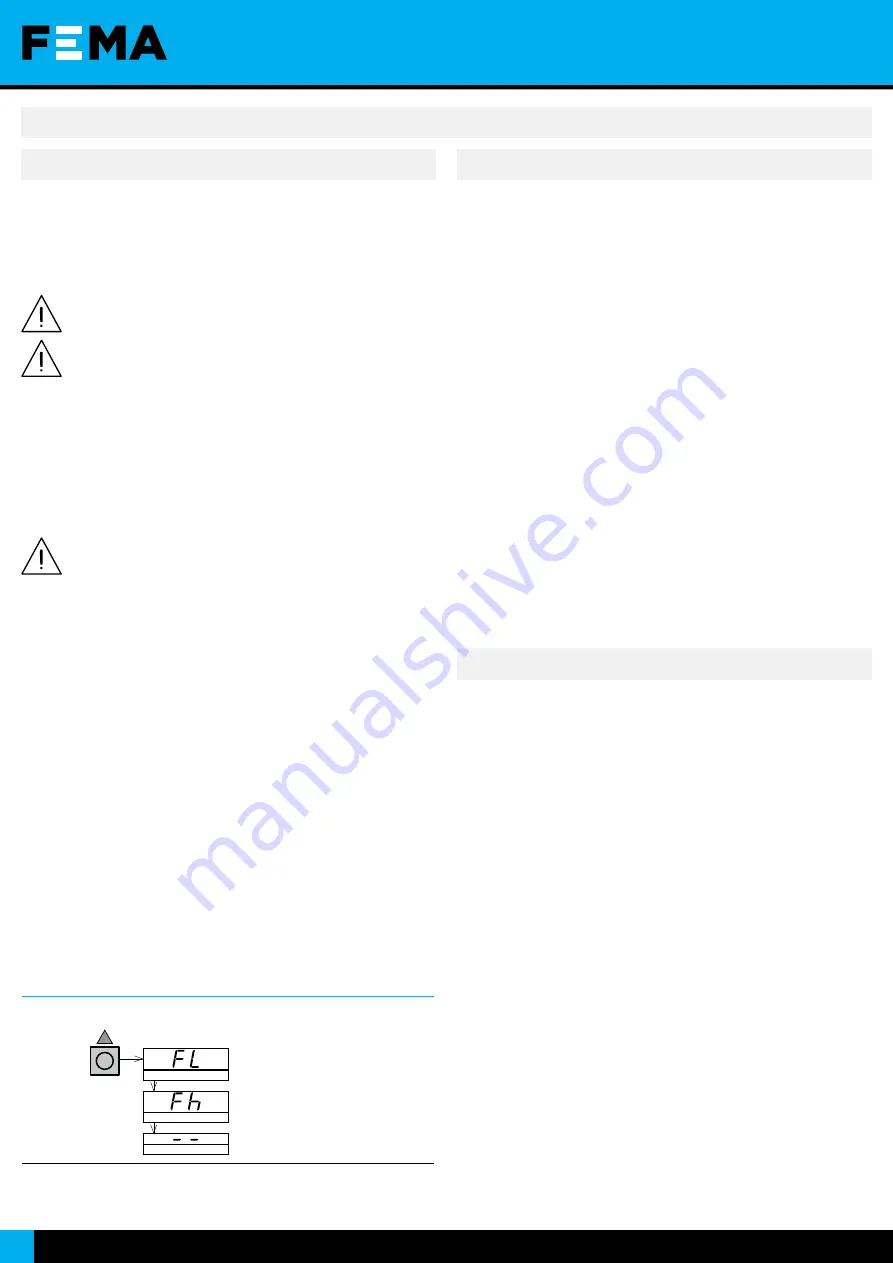
Table 6
|
‘Tools’ menu
UP
Press ‘
UP
’ (
5
) for 1 second to access the
‘
tools
’ menu.
‘Force Low’
‘Force high’
Exit
9. Operate the configuration system (cont.)
HOW TO BLOCK ACCESS TO ‘CONFIGURATION MODE’ (‘PASSWORD’)
Define a ‘
password
’ code to prevent access to ‘
configuration mode
’ and
to ‘
tools
’ menu to unauthorized operators. The ‘
password
’ code will be
requested when trying to access the ‘
configuration mode
’ or the ‘
tools
’
menu.
To activate a ‘
password
’ select code ‘
15
’ inside the ‘
configuration mode
’.
The step-by-step process is indicated below:
• access the ‘
configuration mode
• access code ‘
15
’
• press the ‘
SQ
’ (
<
) key to select
• the ‘configuration digits’ indicate code ‘
00
’ flashing
• press the ‘
UP
’ (
5
) key to select the desired code (for example ‘
73
’)
• press the ‘
SQ
’ (
<
) key to validate or wait for the automatic ‘
rollback
’
(60 seconds) to exit without changes
• the menu returns ‘
normal mode
Once the ‘
password
’ code is applied, when a key is pressed, the
‘
configuration digits
’ indicate code ‘
00
’ flashing. Enter the ‘
password
’
code to unlock access (code ‘
73
’ in the previous example).
HOW TO DEACTIVATE THE ‘PASSWORD’
To deactivate the ‘
password
’, access again to code ‘
15
’ and select value
‘
00
’. Press ‘
SQ
’ (
<
) key to confirm.
10.4. Configuration block (‘password’)
The instrument can be configured to work with a slower or faster mode.
The slower mode will have an improved accuracy in most of the working
range. Configure code ‘
18
’ ‘
Working mode
’ and select the value to ‘
01
’ for
a standard response time of 200 mSec or select ‘
02
’ for a response time
of 550 mSec and an improved accuracy in most of the working range.
HOW TO SET THE ‘WORKING MODE’ PARAMETER
To configure the ‘
working mode
’ value, access code ‘
18
’ inside the
‘
configuration mode
’. The step-by-step process is indicated below.
• access the ‘
configuration mode
• access code ‘
18
’
• press the ‘
SQ
’ (
<
) key to select
• the ‘configuration digits’ indicate code ‘
01
’ flashing
• press the ‘
UP
’ (
5
) key, to select value ‘
01
’ or ‘
02
’
• press the ‘
SQ
’ (
<
) key to validate or wait for the automatic ‘
rollback
’
(30 seconds) to exit without changes
• the menu returns ‘
normal mode
10.5. Working mode
Содержание I3 Series
Страница 11: ...SERIES I3 Model I3D Section OEM ISOLATED SIGNAL CONVERTERS www fema es 11 Notes...
Страница 12: ......


