background image

39

Reference

Fellowes

        Description

No.

Part No.

Bin (basket) full light sensor

220283

31690

Plastic wiring clip

111701

31621

I/R front fixture

220502

31640

I/R support

250502

31667

Powershred lubricant (12 oz. bottle)

35250

Waste Bags (dispenser, 50/roll)

36054

Miscellaneous

220-2 and 220C-2 Parts Lists - continued

Содержание 220-2

Страница 1: ...0C 2 C 220 C 220C June 2007 For all models up to and including 38221 Rev D 32221 Rev B 38221 71 Rev C 38221 72 Rev C 38221 73 Rev C 38222 71 Rev B 38222 72 Rev C 38222 73 Rev B 32222 Rev C 38225 71 Rev D 38225 72 Rev D 38225 73 Rev D 38225 Rev E ...

Страница 2: ......

Страница 3: ... 2 220C 2 C 220 C 220C For all models up to and including 38221 Rev D 32221 Rev B 38221 71 Rev C 38221 72 Rev C 38221 73 Rev C 38222 71 Rev B 38222 72 Rev C 38222 73 Rev B 32222 Rev C 38225 71 Rev D 38225 72 Rev D 38225 73 Rev D 38225 Rev E ...

Страница 4: ......

Страница 5: ...ion 4 Operation 4 Troubleshooting 5 Paper Feed Problems 5 Electrical Problems 6 Mechanical Problems 7 Troubleshooting Flowcharts 7 Tools and Supplies 12 Cabinet and Housing 13 Replace Caster Assembly 13 Remove Housing Cover 14 Remove Replace PC Board 15 Mechanical Assemblies 16 Remove Cutting Assembly and Motor from Cabinet 16 Remove Cutting Assembly Gears 17 Remove Motor 18 ...

Страница 6: ...2 and C 220C Cutting Assembly 24 Electrical Assemblies 25 Replace Capacitor 25 Replace Power Cord 26 Replace Basket Full Sensor 27 Replace Door Closed Switch 28 Replace Operator Panel Switches 29 Troubleshooting LEDs 29 Replace Paper Feed Sensor 30 Current Limit Adjustment 31 Wiring Diagrams 33 Parts Lists 35 Cabinet and Housing 36 Motor 36 Cutting Assembly 37 Gear Box and Gears 38 Electrical Comp...

Страница 7: ...tly If there are no specific instructions for reassembling an item simply reverse the disassembly procedure From the service and repair perspective the 220 2 and 220C 2 models are similar except for the cutting assemblies The 220 2 and C 220 are strip cut shredders The 220C 2 and C 220C are confetti cut shredders The maximum paper size for the shredders is standard letter and A size paper The shre...

Страница 8: ...nto the paper feed slot or throat n Keep all loose articles of clothing ties jewelry long hair or other loose objects away from the paper feed slot n Always turn off and unplug the power cord at the wall outlet before doing any work on a shredder n Use only the specified replacement parts See the Parts List beginning on page 35 Wall Mounting Each 220 2 and C 220 shredder includes a wall mounting k...

Страница 9: ...xterior of the shredder Internal Cleaning The shredder does not require periodic internal cleaning However when the shredder is being serviced perform the following maintenance tasks n Remove any paper strips or pieces that may have collected around the cutting assembly n If lubricated parts are dusty wipe away the dust with a soft cloth n Use a small brush or vacuum to remove dust from the non lu...

Страница 10: ...of the paper feed slot starting at one end of the paper feed slot Operation The operator panel is located on the shredder cover The panel consists of two control switches and troubleshooting indicator lights Operator Panel Control Switches I Automatic Turns on the automatic start sensor and the the green Ready light O Off Turns off the automatic start sensor and the green Ready light R Reverse Run...

Страница 11: ... material through the machine If the paper jam light is on follow these steps until the light turns off 1 Unplug the shredder 2 Check the wastebasket and empty if full Replace the basket and make sure the drawer closed switch is fully engaged 3 Plug in the shredder Press and hold the control switch in reverse position to back paper out of the paper feed slot Try pulling gently on the paper to remo...

Страница 12: ... needed to clear the birdnest Electrical Problems The most common electrical problems result from an opened waste basket drawer loose wires or a defective PC board If the wastebasket is not properly in place the shredder will not operate The Basket Ajar LED will help to identify this problem Check the drawer to make sure it properly engages and closes the basket ajar switch Press the Auto On I swi...

Страница 13: ... feed paper through the shredder See the Lubrication instructions in the General Maintenance section of this manual for additional instructions If these simple solutions do not solve the problem then use the following troubleshooting checklists to help identify and solve the problem Troubleshooting Flowcharts This section includes four flowcharts that begin with a typical shredder problem Flowchar...

Страница 14: ...le at wall outlet Connect any loose wires Check for loose or defective wires Replace paper basket Press forward and auto on reverse switch to clear jam Procedure Replace Power Cord Procedure Replace Basket Ajar Switch Check for loose internal electrical connections Replace sensor if defective Replace basket full sensor or basket ajar switch if defective Allow m otor to cool then restart shredder P...

Страница 15: ...s beyond capability of shredder Drive gears are stripped or dam aged No action required Replace gears as needed No only thin paper Procedure Rem ove Cutting Assem bly Gears Replace m otor if dam aged Procedure Rem ove M otor Motor gear is stripped or dam aged Unable to cut tissue carbon or other paper Yes ...

Страница 16: ... cylinders Damaged cutting assembly gears Debris on cutting cylinders Replace dam aged dust covers or stripping devices Replace dam aged cutting cylinders Replace dam aged cutting assem bly gears Rem ove debris Procedure Rem ove Cutting Assem bly Gears Rem ove cutting assem bly to clear debris Procedure Repair Cutting Assem bly Procedure Repair Cutting Assem bly ...

Страница 17: ...Replace M otor Motor problems Rem ove debris Rem ove cutting assem bly to clear debris Procedure Rem ove Cutting Assem bly Debris in cutting assembly Procedure Repair Cutting Assem bly Motor operates but without force or direction Replace capacitor Procedure Replace Capacitor Capacitor problem Flowchart D ...

Страница 18: ...ls 220 2 220C 2 C 220 and C 220C Screwdrivers Flat blade screwdrivers Phillips screwdrivers Pliers Long nose pliers Wrenches Sockets Socket wrenches w extension Hammers Plastic end hammer Rubber mallet Miscellaneous Gear puller Supplies Cleaning solvent Cutting oil Gloves optional Gear grease Loctite Tape Tie wraps ...

Страница 19: ...ssembly The caster assembly screws into a threaded socket on the bottom of the cabinet 1 Remove the wastebasket 2 Select a suitable work surface and put a blanket mat or other cover down to prevent damage to the shredder 3 Lay the shredder on its side on the blanket 4 Turn the nut clockwise to remove the caster from the bottom of the cabinet 5 Replace the old caster with a new one DO THIS FIRST Un...

Страница 20: ...ket 2 Remove the 3 screws that hold the cover to the lip at the front of the cabinet 3 Grip the housing cover on both sides then gently lift and push the cover toward rear of the unit to release the rear latches Note Be careful The latches are plastic and may break if too much force is applied 4 Set the cover aside DO THIS FIRST Unplug the Shredder TOOLS Phillips screwdriver cable connects to PC b...

Страница 21: ...oard See wiring diagrams 2 Disconnect the basket full sensor wires from the PC board 3 Lift the paper feed sensor wires out of the channels along the cutting cylinders see wiring diagrams and remove the sensor wires from channels located along the cutting cylinder shroud 4 Disconnect the black and blue wire tabs from the capacitor 5 Disconnect the red yellow and black motor wire tabs from the PC b...

Страница 22: ...g assembly and motor 1 Remove the screw that holds the motor ground wire yellow green to the cabinet shelf 2 Remove the 2 screws under the cabinet shelf that hold the motor mount to the cabinet 3 Remove the 4 nuts locking washers spring gaskets washers and rubber pads from the stove bolts that hold the front and rear bearing plates to the cabinet 4 Lift the assembly out of the cabinet and place it...

Страница 23: ... the 6 screws and washers that hold the gearbox cover to the left bearing plate 2 Pull the gear box cover away and up from the bearing plate The small white gear and the gray drive gear will remain on the gear box shaft 3 Remove the large white gear and washer from the cutting cylinder shaft DO THIS FIRST Remove Cutting Assembly and Motor from Cabinet TOOLS Philips screwdriver Gear puller right be...

Страница 24: ...connected from the cabinet shelf 3 Remove the small drive gear from the motor shaft 4 Remove the 3 bolts and washers that hold the motor to the left bearing plate 5 Support the bearing plate and cutting assembly as you remove the motor Note Go to the cutting assembly procedures for the model you are servicing DO THIS FIRST Remove Cutting Assembly Gears TOOLS Philips screwdriver Motor motor drive s...

Страница 25: ...ected by the stripper shrouds and strippers Four distance shafts hold the cutting assembly together and attach to the left and right bearing plates stripper shrouds 2 small cutting shaft assembly distance shafts 4 left bearing plate strippers 2 journal bearing inset large cutting shaft assembly 220 2 and C 220 Cutting Assembly right bearing plate ...

Страница 26: ...embly 5 Pull up and out on the stripper shrouds and remove them from the cutting shafts 6 Remove the 2 screws that hold the journal bearing insert to the right bearing plate 7 Push the cutting shaft assmblies toward the right bearing plate and push the journal bearing inset out of the opening 8 Remove the strippers from the cutting shafts 9 Slide the cutting shaft assemblies through the opening in...

Страница 27: ... 5 Slide the upper and lower distance shafts through the stripper shrouds and strippers Replace the 4 screws and washers that hold them to the left bearing plate 6 Slide the right bearing plate over the cutting shafts 7 Replace the 4 screws and washers that hold the distance shafts to the right bearing plate 8 Place the large white gear over the large cutting shaft gear 9 Place the small white gea...

Страница 28: ...ipper shrouds and 2 strippers Four distance shafts hold the cutting assembly together and attach to the right and left bearing plates 220C 2 and C 220C Cutting Assembly stripper shroud right bearing plate strippers 2 stripper shroud left bearing plate distance shafts 4 small cutting shaft large cutting shaft 220C 2 and C 220C Cutting Assembly ...

Страница 29: ...e the 4 screws and washers that hold the distance shafts to the left bearing plate 3 Remove the right bearing plate 4 Slide the distance shafts out of the cutting assembly 5 Pull up and out on the stripper shrouds to remove them from the cutting shafts 6 Pull down and out on the strippers to remove them from the cutting shafts 7 Remove the 2 screws that hold the journal bearing inset to the rear b...

Страница 30: ...late 5 Fit the stripper shrouds and strippers into position along the cutting shafts 6 Slide the distance shafts through the strippers and replace the bolts and washers that hold them to the left bearing plate 7 Slide the right bearing plate over the cutting shafts 8 Replace the bolts and washers that hold the top and bottom distance shafts to the front bearing plate 9 Place the large white gear o...

Страница 31: ...om the power source To replace the capacitor 1 Disconnect the 2 wires that connect the old capacitor to the PC board Note the color and location of these wires Note Be careful not to damage the PC board or the wires connected to it 2 Remove the 2 screws that hold the capacitor to the cabinet shelf Remove the old capacitor 3 Attach the new capacitor to the base plate with the screws 4 Connect the 2...

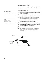
Страница 32: ...and remove the wire guide 4 Push the the power cord and strain relief through the opening at the back of the cabinet 5 Place the new power cord in the cabinet opening 6 Place the wires inside the wire guide and reattach the wire guide to the cabinet shelf 7 Reconnect the wires 6 Reattach the power cord wires to the PC board after replacing the motor and cutting cylinder assembly DO THIS FIRST Remo...

Страница 33: ...C board See the wiring diagram 2 Remove the screw that holds each basket full sensor bracket to the bottom of the cabinet shelf Remove the lamp from the bracket Note the color of each lamp 3 Thread the new transmitter or receiver lamp through the opening in the cabinet shelf and place the lamp in the bracket 4 Place the brackets in position on the bottom of the cabinet shelf making sure the 2 plas...

Страница 34: ...start until the door is closed properly Two screws hold the switch to a supports on the cabinet shelf Three wires from the switch blue green and black are hard wired to PC board The entire PC board must be replaced if this switch is defective see the wiring diagrams To replace the drawer closed switch 1 Remove the 2 screws that hold the door closed switch to the inside of the PC board support base...

Страница 35: ... cover 2 Lift the insert up and away from the cover 3 Put the new insert in place and secure it to the housing cover Troubleshooting LEDs Three troubleshooting LEDs door ajar basket full and paper jam fit into supports attached to the PC board Another LED ready indicator is mounted directly on the PC board If a troubleshooting LED or the ready LED fails replace the entire PC board See Remove Repla...

Страница 36: ... and receiver are in the same position Then make sure the lamps are properly aligned so that they will activate the shredder when paper is put in the paper feed slot To replace the paper feed sensor 1 Place the new transmitter and receiver lamps in the holders located on either side of the paper feed slot 2 Attach the sensor wires in the wire guides located along the cutting cylinder assembly 3 Ma...

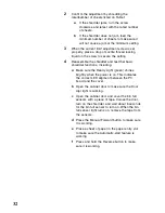
Страница 37: ...tin 220 2 Current Limit Adjustment To check and adjust the current limit setting 1 Attempt to shred the minimum jam quantity listed on Table 1 a If the machine shreds without jamming turn the current limit adjustment screw on the PC board counterclockwise Repeat step 1 b If the machine jams the red paper jam light goes on and the shredder runs in reverse for one second to clear the jam go to step ...

Страница 38: ...tions including a Make sure the Ready Light green shines brightly when the power is on This indicates the correct LED aligment between the PC board and the cover b Open the cabinet door to make sure the Door Ajar light is working c Open the cabinet door and cover the bin full sensors with a piece of tape Colose the door turn on the shredder and wait about 8 seconds for the bin full sensor to turn ...

Страница 39: ...r Closed Switch Motor Paper Feed Slot Basket Full Sensor right white black black red green yellow Paper Jam Sensors Power Cord Ground blue blue black green black white green red yellow black black cable to operator panel switches orange blue black orange Basket Full Sensor left Ground ...

Страница 40: ...k blue red green blue black black red blue orange white blue black orange cable to operator panel switches green yellow yellow black Motor Ground Door Closed Switch Capacitor PC Board Paper Jam Sensors Basket Full Sensor left Basket Full Sensor right current limit adjustment screw Power Cord ...

Страница 41: ...35 Parts List page Models 220 2 220C 2 C 220 and C 220C Cabinet 36 Motor 36 Cutting Assembly 37 Gear Box and Gears 38 Electrical Components 38 Miscellaneous 39 ...

Страница 42: ...er insert w control panel gray sc 280102 1 280105 31735 cc 280102 2 280105 31736 Cover insert w control panel blue black sc 280102 5 280105 1 205689 cc 280102 6 280105 1 205691 Wastebasket assembly not shown 280923 205073 Caster 1 each not shown 280207 31741 Plastic magnet holder not shown 31743 Door magnet 280918 205458 Wall mounting kit not shown 280220 31742 Door magnet kit not shown 205459 Mot...

Страница 43: ...t assembly 5 8 sc 230721 31630 3 9 sc 220721 31676 cc 250741 31672 8 Short cutting shaft assembly 5 8 sc 230821 31631 3 9 sc 220821 31677 cc 250841 31673 9 Distance shafts sc 4 cc 2 bottom 220402 31628 cc only 2 top 250402 31669 Long shaft spacer not shown sc 220312 31612 cc 250312 31659 Cutting block complete left right bearing assemblies long short cutting shaft assemblies 5 8 sc 31658 3 9 sc 31...

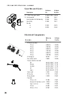
Страница 44: ...31728 UK 280274 220221 31727 Japan 280273 220221 31729 Strain relief 220221 31694 Wiring clip 111701 31621 Wiring harness 220218 31649 Capacitor 120v sc 5 8 220264 31651 Europe UK Australia sc 5 8 220262 31652 Japan cc 3 9 sc 270261 31653 120v cc 230262 31674 230v cc 3 9 sc 220261 31675 Electrical Components Reference Fellowes Description No Part No 12 1st 2nd stage gear combo 220304 229395 205992...

Страница 45: ...sket full light sensor 220283 31690 Plastic wiring clip 111701 31621 I R front fixture 220502 31640 I R support 250502 31667 Powershred lubricant 12 oz bottle 35250 Waste Bags dispenser 50 roll 36054 Miscellaneous 220 2 and 220C 2 Parts Lists continued ...

Страница 46: ...1789 Norwood Avenue Itasca IL 60143 998 telephone 630 893 1600 fax 630 893 7527 1 800 955 3344 ...

Отзывы: