13
ENGLISH
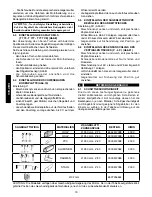
CAUTION - The use of this locking device disables the
safety device provided by the manufacturer and enables
pushbutton start. We advise that this device be used with
maximum care and ONLY when the machine is used as
a circular saw.
To release the lock button again just press it all the way
down and then let it out.
6.6 USING THE END-STROKE SHAFTS (fig.13)
The machine is equipped with end-stroke shaft
A
, which
allows listels or beams to be series cut to uniform length
with maximum precision.
- Insert shaft
A
into the right or left hand support plate,
locking in position with knob
B
.
- Loosen the knob which holds the two shafts together,
adjusting them until the desired length has been
obtained, then lock into position.
In this manner the work piece will always be cut to the
same length.
6.7 USING THE CLAMP
6.7.1 CLAMP 6969000000 (fig.18)
This clamp can be used for the T771-T770-T778-T777
models.
In order to use the clamp, proceed as follows:
- Raise the machine to gain access to the parts beneath
the base.
- Remove the rubber plug fitted at the front and insert
the nut in the hole, then tighten the first screw on the
bracket and replace the rubber plug.
- Insert the other nut in the special seat fitted under the
base and then tighten the second retaining screw.
- Secure the clamp to the bracket, inserting the special
washers.
Rapid feeding (A - fig. 28):
- Press the red push button located above the clamp and
press the threaded pin forward.
Micro-metric feeding (B - fig. 28):
- Simply tighten the threaded pin with the special lever.
6.7.2 CLAMP 6976000000 (fig 23-29)
This clamp can be used for the T778 CE - T 777 CE
models.
- Raise the machine to gain access to the parts beneath
the base.
- Fit the M6 nuts in their seat (fig. 22).
- Position the guide rod, insert 4 screws and spacers
A
(photo 22) and securely fasten bar
B
(fig. 22).
- Insert the clamp in the guide and fasten it with the lever
C
(fig.23-29).
Rapid feeding:
- For rapid feeding unscrew lever
A
( fig.23) and push
the pin forward.
Micro-metric feeding:
Simply tighten the threaded pin with special lever
B
.
CAUTION! - This type of clamp must be fitted when
cutting steel sections.
6.8 USING THE UPPER SURFACE
CAUTION - It is absolutely forbidden to use the upper
surface for cutting steel and aluminium.
CAUTION - It is absolutely forbidden to use the upper
surface without using the lower blade protection.
In order to use the upper surface, proceed as follows:
- Make sure that lock button
E
( fig. 1) is disengaged (in
the protruding position).
- Insert protective casing
B
(fig 17) on support
A
.
- Lower the blade unit completely and lock in position
with pin
A
(fig.9).
- Release levers
B
(fig.9) and select the height of upper
surface, then lock the levers into position once more.
6.9 USING THE END-STROKE GUIDE FOR THE
UPPER SURFACE (fig. 25)
To use, act as follows:
- Fit guide
A
(fig. 25) in the upper surface.
- Select the cut width by means of the graduated scale.
- Lock guide
B
with lever
A
, making sure that the guide
is aligned with the blade.
- For misalignment you can use spanner
E
on screws
C
.
6.10 USE OF MITRE SAWS T777 CE AND T778 CE
These mitre saw models are equipped with an electronic
module which considerably improves the machine
performance.
With this system it is not only possible to cut wood and
aluminum section bars, but also steel sections and bars.
6.10.1 USING THE ELECTRONIC MODULE
This module enables the blade to start slowly (SOFT
START) in order to increase operator safety and maintain
the number of motor revolutions constant in relation to the
pressure exerted on the blade during operation, thereby
improving quality.
Adjusting blade speed:
By means of the orange wheel on the handgrip it is
possible to vary the number of revolutions according to
the type of material to be cut (fig. 32).
6.10.2 CUTTING THE WOOD (WOOD)
- Set the orange wheel to “6” which corresponds to
maximum speed (~ 4 000 r.p.m.), fit the blade for
cutting wood (see the table) and proceed with cutting
operations.
6.10.3 CUTTING ALUMINUM SECTIONS (ALU)
- Set the orange wheel to 3-4 which corresponds to
~ 3000 r.p.m. (see data plate on handgrip), fit the
appropriate blade (see table), lock the section using
the clamp p/n 6976 000000 and proceed with cutting
operations.
6.10.4 CUTTING STEEL SECTIONS AND BARS
(STEEL)
- Set the orange wheel to 1-2 which corresponds to ~
2000 r.p.m. (see data plate on the handgrip); fit the
appropriate blade (see table ) and mount clamp p/n
6976000000 as close as is possible to the blade, in
order to prevent vibration and stop the working piece
from moving - which might otherwise damage the
machine and cause injury to the operator.
Содержание T770
Страница 3: ...1 2 3 4 5 6 7 G D C E H I A K L M B F F A B C E D...
Страница 4: ...13 12 15 14 10 9 8 11 B C A D A B C A B A A B C D B A A A B C...
Страница 5: ...21 20 23 22 18 17 16 19 A B A B C B A C A C B A B A B C...
Страница 6: ...30 28 25 24 29 A B C 32 31 B A A B A B A B C C C E...
Страница 7: ...T 771 T 778 T 770 T 777 T 777 CE T 778 CE...
Страница 55: ...48 K FELISATTI elettroutensili S p A...
Страница 57: ...50 K...
Страница 59: ...52 K...
Страница 60: ...53 K...
Страница 61: ...54 K...
Страница 62: ...55 K...
Страница 99: ...T770 Serie 103 400 FELISATTI 03 02 T 771 03 02 FELISATTI...
Страница 100: ...T777 Serie 104 500 FELISATTI 03 02 FELISATTI MOTORE T 777 03 02...
Страница 101: ...T777CE Serie 400 FELISATTI 03 02 FELISATTI MOTORE T 777 CE 03 02...
Страница 102: ...T 778 Serie 104 FELISATTI 03 02 FELISATTI MOTORE T 778 03 02...
Страница 103: ...T 778 CE FELISATTI 03 02 FELISATTI MOTORE T 778 CE 03 02...


