You will need two boards; both 2” x 4” x 1 ft would be acceptable. If they have no
planed surfaces, you will need to plane one face of each board on the joiner first.
Set the appropriate height for the planer table and lock it into place. Pass the boards
through the planer, one on either side of the table, then check the front and end of
the workpiece for a slightly deeper cut than is elsewhere. Snipe will occur 30 to
60mm from either end of the workpiece if it occurs at all.
If there is no sign of snipe, the next machine check can be made.
If snipe does occur, it will be necessary to make an adjustment to the feed rollers.
The feed rollers are mounted onto springs. If the springs on one of the feed rollers
are set too tight, there will be too much pressure on one side of the table, causing the
table to tip when the workpiece first moves underneath it and then when the
workpiece leaves that feed roller. Contrary to this, if one of the feed rollers is not set
tight enough, there will not be enough force to hold the workpiece down flat on the
table, meaning the workpiece will tip.
This is what causes snipe – the movement of the workpiece (not necessarily the
table) under the cutterblock
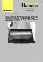
Figure PL02.1
Adjust
ments
PL02 Test for Snipe
Содержание Hammer
Страница 1: ...Machine Setup Guide InstallVersion1 09...
Страница 5: ...15 Completion You re Good To Go 16 FAQ s 17 Links Contact Details Contents 3...
Страница 32: ...The rip fence side is complete 11 Assembly...
Страница 60: ...Test Point Unit type Tolerance Target No snipe Metric Imperial Alignments Adjustme nt Link JR07 Snipe Check...
Страница 74: ...Figure SS03 2 End position 2 Adjustments Alignme nt Link SS03 continued...
Страница 79: ...Figure SS07 3 Crosscut stop and block adjustment Adjustments Alignme nt Link SS07 continued...

