background image

CG15-125BL (**) 

7 222 ...

CG15-150BL (**) 

7 222 ...

CG15-125BLP (**) 

7 222 ...

CG15-150BLP (**) 

7 222 ...

CG15-125BL Inox (**) 

7 222 ...

CG15-125BLP Inox (**) 

7 222 ...

3 41 01 338 21 0

2023-05-09

English (en)
Français (fr)
Español (es)

Содержание CG15-125BL Inox Series

Страница 1: ...CG15 125BL 7 222 CG15 150BL 7 222 CG15 125BLP 7 222 CG15 150BLP 7 222 CG15 125BL Inox 7 222 CG15 125BLP Inox 7 222 3 41 01 338 21 0 2023 05 09 English en Fran ais fr Espa ol es...

Страница 2: ...2 Instruction Manual Mode d emploi Instrucciones de uso en 3 fr 34 es 66...

Страница 3: ...ion can cause you to lose control 2 Electrical safety a Power tool plugs must match the out let Never modify the plug in any way Do not use any adapter plugs with earthed grounded power tools Unmodifi...

Страница 4: ...nd off Any power tool that cannot be controlled with the switch is dangerous and must be repaired c Disconnect the plug from the power source and or the battery pack from the power tool before making...

Страница 5: ...or install an undamaged accessory After inspecting and installing an accessory position yourself and bystanders away from the plane of the rotating accessory and run the power tool at maximum no load...

Страница 6: ...rs sharp edges or bouncing have a tendency to snag the rotat ing accessory and cause loss of control or kickback Do not attach a saw chain woodcarving blade or toothed saw blade Such blades cre ate fr...

Страница 7: ...s can easily penetrate light clothing and or skin If the use of a guard is recommended for wire brushing do not allow any interference of the wire wheel or brush with the guard Wire wheel or brush may...

Страница 8: ...tool s lamp from a short distance Never point the light of the lamp into the eyes of other persons in close vicinity The radiation produced by the lamp can be harmful for the eye After working gypsum...

Страница 9: ...boat and ship hulls Stainless steel dust metal dust and non ferrous metal dust To minimize the unwanted intake of these materials Use dust extraction matched appropri ately for the developing dust Us...

Страница 10: ...sed for a pre liminary assessment of exposure The declared vibration emission level repre sents the main applications of the tool However if the tool is used for different applications with different...

Страница 11: ...97 5 97 0 97 4 Measuring uncertainty KwA in decibels 3 3 3 3 3 Vibrations Mean vibrational value for angle grinding in m s2 ft s2 5 1 16 7 4 2 13 8 5 1 16 7 4 2 13 8 4 2 13 8 Mean vibrational value fo...

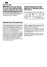
Страница 12: ...ing the application tools and accessories recommended by FEIN This power tool is also suitable for use with AC generators with sufficient power output that correspond to the Standard ISO 8528 design t...

Страница 13: ...se ear protection during operation Use protective gloves during operation Always operate the power tool with both hands A surface that can be touched may be very hot and thus hazardous This symbol con...

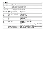
Страница 14: ...Explanation n min min 1 rpm r min Rated speed P W Electrical power U V Electric voltage f Hz Frequency I A Electric current intensity ft in mm Diameter of a round part K Uncertainty m s2 Vibrational e...

Страница 15: ...s out the danger of injuries through acci dental starting of the power tool Not all accessories described or shown in this instruction manual will be included with your power tool WARNING On Off switc...

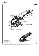
Страница 16: ...16 en On Off switch Locking button Grinding disc Protection guard Gripping surface Auxiliary handle CG15 125BLP CG15 150BLP CG15 125BLP Inox Eyelet for securing cable Fig 2...

Страница 17: ...1 4 in 1 mm 6 mm 1 16 in 1 4 in 1 mm 6 mm TB 3 safety cover B 3 1 16 in 1 8 in 1 mm 3 mm 1 16 in 1 12 in 1 mm 2 mm 1 16 in 1 8 in 1 mm 3 mm 1 16 in 1 12 in 1 mm 2 mm 1 16 in 1 8 in 1 mm 3 mm Max sand...

Страница 18: ...nting the wheel guard figure 4 For all work please refer to figure 13 Insert the wheel guard ensuring that the cams of the opening engage in the grooves on the power tool Press the clamping lever and...

Страница 19: ...en both engaging hooks Remove the safety cover Mounting the safety cover figure 6 Slide the safety cover over the wheel guard Pay attention that the two engaging hooks are fully engaged Safety cover F...

Страница 20: ...the maximum load specified on the secur ing cable Otherwise serious or fatal inju ries may result Observe the safety and operating instruc tions enclosed with the securing cable Connect the securing...

Страница 21: ...inding accessory or insert a new one Pay attention that the grinding acces sory is properly centered between the support flange and the quick clamping nut Manually screw the quick clamping nut on agai...

Страница 22: ...easure rules out the danger of injuries through acci dental starting of the power tool Adjusting the wheel guard figure 9 Release clamping lever Turn the wheel guard to the requested working position...

Страница 23: ...e application tool for damage Afterwards switch the power tool on again The electronic overload protection reduces the risk of motor damage if the power tool is overloaded In this case the power tool...

Страница 24: ...lanation On Opera tional readiness Normal condition as soon as plug is con nected to mains also during operation Flash ing Thermal overload Warning against and signalling of thermal overload shut off...

Страница 25: ...tool CG15 125BL CG15 150BL CG15 125BL Inox figure 10 Switching on Press and push the On Off switch forward I Switching off Press the switch downward CG15 125BLP CG15 150BLP CG15 125BLP Inox figure 11...

Страница 26: ...12 CG15 125BLP figure 13 Fig 12 Dial control for speed adjustment 1 2 3 4 5 6 9 000 min 7 500 min 5 100 min 3 800 min 6 700 min 5 900 min 4 9 000 min 7 500 min 6 700 min 5 900 min 5 100 min 3 800 min...

Страница 27: ...3 4 5 6 7 000 min 5 700 min 3 900 min 2 800 min 5 100 min 4 500 min 4 7 000 min 5 700 min 5 100 min 4 500 min 3 900 min 2 800 min 3 2 1 5 6 Fig 15 1 2 3 4 5 6 7 000 min 5 700 min 3 900 min 2 800 min...

Страница 28: ...piece to fall down and lead to other dangerous situations Dry grinding figure 17 Observe a lead angle of 20 40 This will ensure a good removal rate Apply uniform pressure with the power tool and move...

Страница 29: ...ckers and warning indications on the power tool when aged and worn The current spare parts list for this power tool can be found in the Internet at www fein com Use only original spare parts Service H...

Страница 30: ...instruction manual will be included with your power tool Environmental protection disposal Packaging worn out power tools and accessories should be sorted for environmental friendly recycling Dispose...

Страница 31: ...c hubbed wheel use only with mounted wheel guard 2 1 Cutting disc use only with mounted safety cover 3 1 Flap disc 3 2 Backing pad for fiber sanding sheets fiber sanding sheets mount only with the pro...

Страница 32: ...32 en Bild 12 Fig 20 B 1 1 1 3 1 4 1 B 1 A 1 2 1 4 1 B 3 B 2 1 2...

Страница 33: ...33 en Bild 12 Fig 21 3 2 3 3 4 2 5 1 P 1...

Страница 34: ...u rit 1 Zone de travail a Maintenir la zone de travail propre et bien clair e Les zones en d sordre ou sombres sont propices aux acci dents b Ne pas faire fonctionner les outils lectrique en atmosph r...

Страница 35: ...nts amples ou de bijoux Garder les cheveux les v te ments et les gants distance des par ties en mouvement Des v tements amples des bijoux ou les cheveux longs peuvent tre pris dans des par ties en mou...

Страница 36: ...r le fabricant d outils Le simple fait que l acces soire puisse tre fix votre outil lectrique ne garantit pas un fonctionnement en toute s curit La vitesse assign e de l accessoire doit tre au moins g...

Страница 37: ...c l accessoire en rotation pourrait s accrocher aux v tements et attirer l acces soire vers l utilisateur Nettoyer r guli rement les orifices d a ra tion de l outil lectrique Le ventilateur du moteur...

Страница 38: ...rasives sont destin es au meulage p riph rique l application de forces lat ra les ces meules peut les briser en clats Toujours utiliser des flasques de meule non endommag s qui sont de taille et de fo...

Страница 39: ...t enflammer ces v tements Utiliser les entretoises si celles ci sont four nies avec la meule Les meules coud es doivent tre mont es de mani re ce que leur surface de pon age soit en retrait de 2 mm pa...

Страница 40: ...trouvant proximit Les rayons g n r s par la lampe peuvent tre dangereux pour les yeux Apr s avoir travaill des mat riaux base de pl tre Nettoyer les orifices de ventila tion de l outil lectrique et de...

Страница 41: ...ussi res de m taux non fer reux Pour minimiser la r sorption ind sirable de ces mat riaux Utiliser une aspiration adapt e la pous si re g n r e Utiliser des quipements personnels de protection tels qu...

Страница 42: ...mplitude d oscillation correspond aux utilisations principales de l outil lectrique Si l outil lectrique est cependant utilis pour d autres applications avec d autres outils de travail ou avec un entr...

Страница 43: ...l 97 5 98 6 97 5 97 0 97 4 Incertitude KwA en d ci bel 3 3 3 3 3 Vibration Valeur de vibration moyenne pour le meu lage d angle en m s2 ft s2 5 1 16 7 4 2 13 8 5 1 16 7 4 2 13 8 4 2 13 8 Valeur de vib...

Страница 44: ...Fein sans utilisation de liquides de refroidissement Cet outil lectrique est galement con u pour fonctionner sur des groupes lectrog nes d une puissance suffisante correspon dant la norme ISO 8528 cla...

Страница 45: ...acoustique Lors des travaux utiliser un prot ge main Toujours utiliser l outil lectrique des deux mains Une surface qui peut tre touch e est tr s chaude et donc dange reuse Ce symbole confirme la cer...

Страница 46: ...W Unit de mesure pour la puissance lectrique U V Unit de mesure pour la tension lectrique f Hz Unit de mesure pour la fr quence I A Unit de mesure pour l intensit du courant lec trique ft in mm Diam t...

Страница 47: ...er de blessure caus par un d marrage non intentionn de l outil lectrique Il se peut que seule une partie des accessoires d crits ou repr sent s dans cette notice d uti lisation soit fournie avec l out...

Страница 48: ...48 fr Interrupteur Marche Arr t Button de blocage Meule Capot de protection Surface de prise Poign e suppl mentaire CG15 125BLP CG15 150BLP CG15 125BLP Inox illet pour protection anti chute Fig 2...

Страница 49: ...n 1 mm 6 mm TB 3 couvercle de protection B 3 1 16 in 1 8 in 1 mm 3 mm 1 16 in 1 12 in 1 mm 2 mm 1 16 in 1 8 in 1 mm 3 mm 1 16 in 1 12 in 1 mm 2 mm 1 16 in 1 8 in 1 mm 3 mm Diam tre max du plateau de p...

Страница 50: ...capot de protection figure 4 Pour tous les travaux voir la figure 13 Montez le nez du capot de protection dans les rainures de l outil lectrique Appuyez sur le levier de serrage et tournez le capot de...

Страница 51: ...ection Retirer le couvercle de protection Monter le couvercle de protection figure 6 Faire glisser le couvercle de protection sur le capot de protection Veiller ce que les crochets d arr t soient enti...

Страница 52: ...positif de protection anti chute Le non respect peut entra ner des blessures graves ou mortelles Respecter les consignes de s curit et les instructions qui accompagnent le dispositif de protection ant...

Страница 53: ...serrage rapide Changer la meule us e ou monter une meule neuve Veiller ce que la meule soit bien cen tr e entre la flasque d appui et l crou serrage rapide Resserrer l crou serrage rapide manuelle men...

Страница 54: ...ve exclut un danger de blessure caus par un d marrage non intentionn de l outil lectrique R glage du capot de protection figure 9 Desserrez le levier de serrage Tournez le capot de protection pour obt...

Страница 55: ...que l accessoire n est pas endommag Ensuite remettre l outil lectrique en marche Le dispositif de protection lectronique contre les surcharges r duit le risque d endommager le moteur en cas de sur ch...

Страница 56: ...c tionner tat normal d s que la fiche est branch e sur le secteur m me pen dant l utilisation Cligno tement Sur charge thermi que Avertissement et signalisation d une coupure thermique en cas de surch...

Страница 57: ...G15 150BL CG15 125BL Inox figure 10 Mise en fonctionnement Appuyez et poussez l interrupteur Mar che Arr t vers l avant I Arr t Pousser l interrupteur vers le bas CG15 125BLP CG15 150BLP CG15 125BLP I...

Страница 58: ...vitesse la plus lev e CG15 125BL figure 12 CG15 125BLP figure 13 Fig 12 Molette de r glage de la vitesse de rotation 1 2 3 4 5 6 9 000 min 7 500 min 5 100 min 3 800 min 6 700 min 5 900 min 4 9 000 mi...

Страница 59: ...3 4 5 6 7 000 min 5 700 min 3 900 min 2 800 min 5 100 min 4 500 min 4 7 000 min 5 700 min 5 100 min 4 500 min 3 900 min 2 800 min 3 2 1 5 6 Fig 15 1 2 3 4 5 6 7 000 min 5 700 min 3 900 min 2 800 min...

Страница 60: ...autres incidents dangereux Pon age sec figure 17 Maintenir un angle d inclinaison de 20 40 Vous obtiendrez ainsi un bon enl vement de mat riau Appuyer l outil lectrique de fa on r guli re et le faire...

Страница 61: ...il lectrique en cas de vieillissement ou d usure Vous trouverez la liste actuelle des pi ces de rechange pour cet outil lectrique sur notre site www fein com N utiliser que des pi ces de rechange d or...

Страница 62: ...il lectrique Protection de l environnement recyclage Rapporter les emballages les outils lectriques hors d usage et les accessoires dans un centre de recyclage respectant les directives concernant la...

Страница 63: ...u avec capot de protection mont 2 1 Disque tron onner n utiliser qu avec capot de protection mont 3 1 Disque lamelles 3 2 Plateau souple pour disques abrasifs en fibre disques abrasifs en fibre monter...

Страница 64: ...64 fr Bild 12 Fig 20 B 1 1 1 3 1 4 1 B 1 A 1 2 1 4 1 B 3 B 2 1 2...

Страница 65: ...65 fr Bild 12 Fig 21 3 2 3 3 4 2 5 1 P 1...

Страница 66: ...y una iluminaci n deficiente en las reas de trabajo pueden provocar accidentes b No utilice la herramienta el ctrica en un entorno con peligro de explosi n en el que se encuentren combustibles l quid...

Страница 67: ...la herramienta el ctrica en caso de presentarse una situaci n inespe rada f Lleve puesta una ropa de trabajo ade cuada No utilice ropa amplia ni joyas Mantenga su pelo ropa y guantes ale jados de las...

Страница 68: ...m nimo iguales a las revoluciones m ximas indicadas en la herramienta el c trica Aquellos accesorios que giren a unas revoluciones mayores a las admisibles pue den llegar a romperse y salir despedido...

Страница 69: ...pas produ cidas al trabajar pueden llegar a incendiar estos materiales No emplee tiles que requieran ser refrige rados con l quidos La aplicaci n de agua u otros refrigerantes l quidos puede compor ta...

Страница 70: ...vocar su rotura Siempre use para el til seleccionado una brida en perfecto estado con las dimensio nes y forma correctas Una brida adecuada soporta convenientemente el til redu ciendo as el peligro de...

Страница 71: ...centro deprimido deber n montarse de manera que la cara de amolar quede 2 mm por debajo del borde inferior de la guarda de protecci n Las muelas que no cumplan con estas exigencias no pueden ser sufi...

Страница 72: ...ser da ina para la vista Tras trabajar en materiales que contengan yeso Limpie las rejillas de refrigeraci n de la herramienta el ctrica y del mando del switch con aire comprimido seco y sin aceite D...

Страница 73: ...de metales no f rricos Para que la exposici n a estos materiales sea m nima Utilice un equipo de aspiraci n apropiado para el polvo producido Use equipos de protecci n personal como por ejemplo una m...

Страница 74: ...de vibraciones indicado ha sido determinado para las aplicaciones principa les de la herramienta el ctrica Por ello el nivel de vibraciones puede ser diferente si la herramienta el ctrica se utiliza...

Страница 75: ...6 97 5 97 0 97 4 Inseguridad KwA en decibelios 3 3 3 3 3 Vibraci n Vibraciones promedio generadas al esmerilar en m s2 ft s2 5 1 16 7 4 2 13 8 5 1 16 7 4 2 13 8 4 2 13 8 Vibraciones promedio generada...

Страница 76: ...ntes l quidos Esta herramienta el ctrica es apta adem s para ser utilizada con grupos electr genos de alterna siempre que dispongan de sufi ciente potencia y cumplan los requisitos seg n norma ISO 852...

Страница 77: ...ico Al trabajar utilizar una protecci n para las manos Siempre trabajar con la herramienta el ctrica sujet ndola con ambas manos Existe el riesgo de quemarse con una superficie muy caliente Este s mbo...

Страница 78: ...Unidad de medida de la potencia U V Unidad de medida de la tensi n el ctrica f Hz Unidad de medida de la frecuencia I A Unidad de medida de la intensidad ft in mm Di metro de una pieza redonda K Ince...

Страница 79: ...rse en caso de una puesta en marcha involuntaria El material de serie suministrado con su herramienta el ctrica puede que no corresponda en su totalidad al material descrito o mostrado en estas instru...

Страница 80: ...80 es Switch Bot n de retenci n Disco de amolar Guarda de protecci n rea de agarre Agarradera adicional CG15 125BLP CG15 150BLP CG15 125BLP Inox Ojillo de seguro antica da Fig 2...

Страница 81: ...4 in 1 mm 6 mm 1 16 in 1 4 in 1 mm 6 mm TB 3 cubierta de protecci n B 3 1 16 in 1 8 in 1 mm 3 mm 1 16 in 1 12 in 1 mm 2 mm 1 16 in 1 8 in 1 mm 3 mm 1 16 in 1 12 in 1 mm 2 mm 1 16 in 1 8 in 1 mm 3 mm D...

Страница 82: ...ontaje de la guarda de protecci n Figura 4 Para todos los trabajos ver figura 13 Aloje los salientes de la guarda de protec ci n en las ranuras de la herramienta el ctri ca Presione la palanca de bloq...

Страница 83: ...otecci n Retire la cubierta de protecci n Montaje de la cubierta protectora Figura 6 Pase la cubierta de protecci n por encima de la guarda de protecci n Cuide que los dos clips de sujeci n queden cor...

Страница 84: ...seguro antica da En el caso contrario ello podr a acarrear lesiones graves o mortales Observe las indicaciones de seguridad y las instrucciones suministradas con el seguro antica da Solo fije el segu...

Страница 85: ...el til Al realizar esto preste atenci n a que el til quede conc ntrico con la brida soporte y la tuerca de sujeci n r pida Vuelva a enroscar a mano la tuerca de suje ci n r pida Presione hasta el fond...

Страница 86: ...los accidentes que pudie ran presentarse en caso de una puesta en marcha involuntaria Ajuste de la guarda de protecci n Figura 9 Afloje la palanca de sujeci n Gire la guarda de protecci n a la posici...

Страница 87: ...inuaci n vuelva a conectar la herramienta el ctrica La protecci n contra sobrecarga electr nica reduce el riesgo de que se da e el motor al sobrecargar la herramienta el ctrica En ese caso la herramie...

Страница 88: ...ido Listo para funcio nar Estado nada m s conectar la clavija a la red y durante el tra bajo normal Intermi tente Sobre tempe ratura Advertencia o indica ci n de sobretempe ratura El usuario es advert...

Страница 89: ...el control sobre la herramienta el ctrica CG15 125BL CG15 150BL CG15 125BL Inox Figura 10 Conexi n Presione y empuje hacia delante el switch I Desconexi n Presione el switch hacia abajo CG15 125BLP CG...

Страница 90: ...y 6 revoluciones m ximas CG15 125BL Figura 12 CG15 125BLP Figura 13 Fig 12 Rueda de ajuste de velocidad 1 2 3 4 5 6 9 000 min 7 500 min 5 100 min 3 800 min 6 700 min 5 900 min 4 9 000 min 7 500 min 6...

Страница 91: ...3 4 5 6 7 000 min 5 700 min 3 900 min 2 800 min 5 100 min 4 500 min 4 7 000 min 5 700 min 5 100 min 4 500 min 3 900 min 2 800 min 3 2 1 5 6 Fig 15 1 2 3 4 5 6 7 000 min 5 700 min 3 900 min 2 800 min...

Страница 92: ...molado en seco figura 17 Gu e la herramienta manteniendo un ngulo de inclinaci n de 20 40 De esta manera conseguir un buen arranque de material Presione uniformemente la herra mienta el ctrica movi nd...

Страница 93: ...ramienta el ctrica si ya no son legibles La lista de piezas de refacci n actual para esta herramienta el ctrica la encuentra en internet bajo www fein com Solo emplee refacciones originales Servicio t...

Страница 94: ...edio ambiente eliminaci n Los embalajes y las herramientas el ctricas y accesorios inservibles deber n entregarse a los puntos de recogida correspondientes para que puedan ser sometidos a un reciclaje...

Страница 95: ...heel usar solo teniendo montada la guarda de protecci n 2 1 Disco de corte solo emplear teniendo montada la cubierta de protecci n 3 1 Disco lijador de l minas 3 2 Plato soporte para discos lijadores...

Страница 96: ...96 es Bild 12 Fig 20 B 1 1 1 3 1 4 1 B 1 A 1 2 1 4 1 B 3 B 2 1 2...

Страница 97: ...97 es Bild 12 Fig 21 3 2 3 3 4 2 5 1 P 1...

Страница 98: ...ww feinus com Canada FEIN Canadian Power Tool Company 323 Traders Boulevard East Mississauga Ontario L4Z 2E5 www fein ca FEIN Service FEIN Power Tools Inc 2735 Hickory Grove Road Davenport IA 52804 ma...

Отзывы: