OBID i-scan
®
Mounting Instruction
ID ISC.ANT340/240-A / -B
FEIG ELECTRONIC GmbH
Page 20 of 28
M10101-3de-ID-B.doc
E N G L I S H
4
Assembly and Wiring
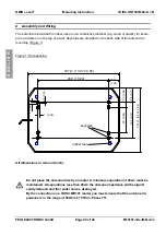
The antenna is intended for indoor use on non conductive material (e.g. wood or plastic) for exam-
ple on a table or on the top of a wall. Keyholes are provided on the back side of the antenna for
mounting (Figure 1)
Figure 1: Hole spacing
All dimensions in mm and (inch).
Do not place the antenna directly on metal. A minimum separation of 20cm must be
maintained. At separations less than 20cm the antenna impedance will be signifi-
cantly detuned and the reader can be destroyed.
By the connection on a ID ISC.MR101 reader you must ensure that the antenna im-
pedance is in the range of 50Ohm ± 15 Ohm, Phase 15°.
337±1 (13,27 ± 0,04)
38,5
(1,52)
90 (3,54)
130 (5,12)
237 ±
1
(9,33 ± 0,04)
10 (0,39)
4,5 (0,18)
7 (0,28)
53,5 (2,11)
73,5 (2,89)
keyholes
rubber feet
260 (10,24)


