background image

OBID

®

Montage

ID RWA02.10-A/-B

Seite 6 von 31

FEIG ELECTRONIC GmbH

D E U T S C H

3.  Montage

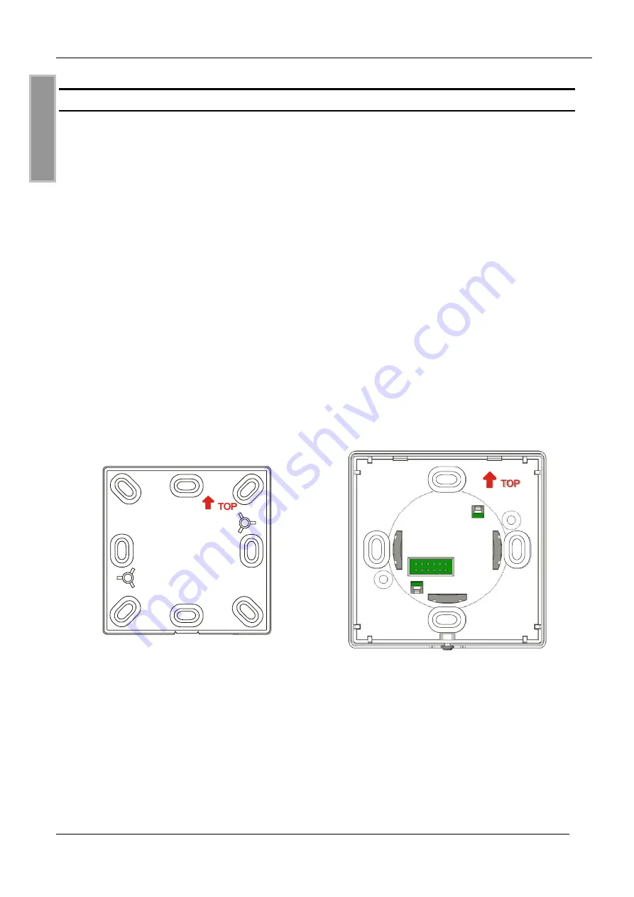
Der Leser ist für die Wandmontage auf 60 mm Unterputzdosen vorgesehen. Der im Lieferumfang
enthaltene Aufputzadapter ermöglicht ein Aufputzmontage auf ebenen Wänden.

HINWEISE:


Der Leser sollte nicht direkt auf leitende Materialien wie Metallflächen, Metallgitter (Ar-
mierung) oder metallisierte Oberflächen montiert werden, da diese Flächen eine Reduzie-
rung der Lesereichweite bewirken..


Bei der Montage auf Metalloberfläche sollte die Montage mit dem Aufputzadapter erfol-

gen, damit ein ausreichender Abstand zwischen Leser und Metalloberfläche hergestellt

ist.


Der räumliche Abstand zu benachbarten Lesern gleicher Bauart sollte 30 cm nicht unter-
schreiten.


Vor der endgültigen Installation sollte der geplante Installationsort auf seine Tauglichkeit
geprüft werden.

Abbildung 1: Aufputzadapter

Montageausrichtung,

(


TOP) nach oben

Abbildung 2: Unterputzgehäuse

Montageausrichtung,

(


TOP) nach oben

Содержание multijob-Reader OBID ID RWA02.10-A

Страница 1: ...MONTAGE INSTALLATION final public B 2008 09 26 M80806 1de ID B doc OBID ID RWA02 10 A ID RWA02 10 B multijob Reader deutsch english...

Страница 2: ...OBID Montage ID RWA02 10 A B Seite 2 von 31 FEIG ELECTRONIC GmbH D E U T S C H deutsche Version ab Seite 3 english version from page 18 E N G L I S H...

Страница 3: ...keine Gew hrleistung f r die Richtigkeit und Vollst ndigkeit der An gaben in diesem Dokument Insbesondere kann FEIG ELECTRONIC GmbH nicht f r Folgesch den auf Grund fehlerhafter oder unvollst ndiger...

Страница 4: ...rgung 9 4 3 Relais 10 4 4 Digitale Eing nge 10 4 5 RS232 Schnittstelle ID RWA02 10 A 10 4 6 RS485 Schnittstelle ID RWA02 10 B 11 4 7 Adresseinstellung Busbetrieb mit RS485 Schnittstelle 12 5 Inbetrieb...

Страница 5: ...rt werden Anschluss Inbetriebnahme Wartungs und sonstige Arbeiten am Ger t d rfen nur von Elektrofachkr ften mit einschl giger Ausbildung erfolgen Alle Arbeiten am Ger t und dessen Aufstellung m ssen...

Страница 6: ...chen montiert werden da diese Fl chen eine Reduzie rung der Lesereichweite bewirken Bei der Montage auf Metalloberfl che sollte die Montage mit dem Aufputzadapter erfol gen damit ein ausreichender Ab...

Страница 7: ...der Wand verschrauben Montagerichtung TOP beachten siehe Kapitel 3 Montage Geh useoberteil gerade auf das Geh useunterteil aufstecken und einrasten Stiftleiste X1 der Leserelektronik sauber in Buchse...

Страница 8: ...WG26 bis AWG18 Empfohlener Au endurchmesser der Anschlussleitung bei Aufputzmontage 7 0 mm Empfohlene Aufbau paarverseilt TP Abbildung 6 Anschlussplatine Klemme Funktion Leiste Bezeichnung ID RWA02 10...

Страница 9: ...V AC oder DC versorgt werden Die Polarit t bei DC Spannungsversorgung kann frei gew hlt werden Bei der Dimensionierung des Netzteils und der Anschlussleitung ist der Spannungsabfall auf der Versorgun...

Страница 10: ...er die Klemmen NO und COM 4 4 Digitale Eing nge Die beiden digitalen Eing nge IN1 bzw IN2 d rfen nur gegen intern GND Klemme GND ge schaltet werden siehe Abbildung 8 Eine Beschaltung mit Fremdspannung...

Страница 11: ...en Leitrechner mit Abschlusswiderstand und aktiver Terminierung voraus Als Leitung wird eine paarweise verseilte oder verdrillte Leitung empfohlen Host ohne Abschlu widerstand R A T B ID RW02 mit akti...

Страница 12: ...en Adresse versehen Adresse DIP 1 DIP 2 DIP 3 DIP 4 0 OFF OFF OFF OFF 1 ON OFF OFF OFF 2 OFF ON OFF OFF 3 ON ON OFF OFF 4 OFF OFF ON OFF 5 ON OFF ON OFF 6 OFF ON ON OFF 7 ON ON ON OFF 8 OFF OFF OFF ON...

Страница 13: ...on dem multijob Reader eingelesen werden 5 2 LED und Beeper Anzeigen Mode Anzeige Beschreibung je 200 ms rot aus gr n aus multijob Reader wartet auf OBID MasterCard 1 x 800 ms gr n Beeper OK OBID Mast...

Страница 14: ...ive Luftfeuchte 95 nicht betauend MTBF 307000 h Antenne intern Betriebsfrequenz 125 kHz unterst tzte Transpondertypen ID CTx A z B H4001 4002 ID DTx B HITAG1 und HITAG S ID DTx C HITAG 2 LED Bicolor r...

Страница 15: ...schl gigen Bestimmungen der R TTE Richtlinie 1999 5 EG vom M rz 99 Equipment Classification gem ETSI EN 300 330 und ETSI EN 301 489 Class 2 6 1 2 USA FCC FCC ID PJMRW02 This device complies with Part...

Страница 16: ...H 6 2 Abmessungen 60 0 mm 60 0 mm 84 2 mm 84 2 mm 77 7 mm 56 8 mm 60 0 mm 28 4 mm 28 4 mm 77 7 mm Abbildung 13 Unterputzgeh use Befestigungsmasse Abbildung 14 Aufputzadapter Befestigungsmasse 84 2 mm...

Страница 17: ...OBID Montage ID RWA02 10 A B FEIG ELECTRONIC GmbH Seite 17 von 31 D E U T S C H...

Страница 18: ...seful tips The instructions given in this manual are based on advantageous boundary conditions FEIG ELECTRONIC GmbH does not give any guarantee promise for perfect function in cross environments and d...

Страница 19: ...Jumper and Switches 24 4 2 Power supply 24 4 3 Relay 25 4 4 Digital inputs IN1 IN2 25 4 5 RS232 Interface ID RWA02 10 A 25 4 6 RS485 Interface ID RWA02 10 B 26 4 7 Address setting Bus mode with RS485...

Страница 20: ...ice Repairs may only be executed by the manufacturer Installation operation and maintenance procedures should only be carried out by qualified personnel Use of the device and its installation must be...

Страница 21: ...al grids reinforcements or metallized surfaces as these surfaces reduce the detection range of the Reader If an installation to a metal surface becomes necessary the surface adapter can be em ployed i...

Страница 22: ...t of casing to selected surface Take care about the mounting direction TOP see chapter 3 Installation Put the casing upper part straight onto its bottom part and snap it in see Fig 4 Insert the pin bo...

Страница 23: ...e which is snapped into the bottom part of the casing connector function board name ID RW02 ABC A ID RW02 ABC B power supply 12 24 AC DC CLS COM NO relay GND internal GND R A RS232 RxD RS485 A X2 T B...

Страница 24: ...The device may be supplied ei ther with 12 24 V AC or DC In case of DC supply the polarity may be chosen freely For the dimensioning of the power supply and the connecting cable the voltage drop on t...

Страница 25: ...and COM 4 4 Digital inputs IN1 IN2 The digital inputs IN1 and IN2 can only be connected to internal GND terminal GND accord ing to Fig 8 connection of the digital inputs Any connection to external vol...

Страница 26: ...d Fig 6 To operate the bus you need a host computer with a terminating resistor and active termination A twisted paired or stranded wire is recommended Host without termination R A T B ID RW02 with ac...

Страница 27: ...ing provided with an individual address Address DIP 1 DIP 2 DIP 3 DIP 4 0 OFF OFF OFF OFF 1 ON OFF OFF OFF 2 OFF ON OFF OFF 3 ON ON OFF OFF 4 OFF OFF ON OFF 5 ON OFF ON OFF 6 OFF ON ON OFF 7 ON ON ON...

Страница 28: ...y be read by the multijob Reader 5 2 LED and beeper signals Mode Signal Description 200 ms at a time red off green off multijob Reader waiting for OBID MasterCard 1 x 800 ms green beeper OK OBID Maste...

Страница 29: ...e air humidity 95 non condensing MTBF 307000 h Antenna integrated Operating Frequency 125 kHz Supported Transponder types ID CTx A e g H4001 4002 ID DTx B HITAG1 and HITAG S ID DTx C HITAG 2 LED bicol...

Страница 30: ...vant provisions of the R TTE Directive 1999 5 EG of March 99 Equipment Classification according to ETSI EN 300 330 and ETSI EN 301 489 Class 2 6 1 2USA FCC FCC ID PJMRW02 This device complies with Par...

Страница 31: ...31 E N G L I S H 6 2 Dimensions 60 0 mm 60 0 mm 84 2 mm 84 2 mm 77 7 mm 56 8 mm 60 0 mm 28 4 mm 28 4 mm 77 7 mm Fig 13 Concealed casing Fixing dimensions Fig 14 Surface adapter dimensions 84 2 mm 84 2...

Отзывы: