background image

3

Installation and Maintenance Manual 

Federal Signal

 www.fedsig.com


Tables

 Table 1  

Specifications

 .................................................................................................................... 8

 Table 2  Parameters ........................................................................................................................ 8
 Table 3  Kit Contents List ............................................................................................................... 8
 Table 4  TAP II Functions ............................................................................................................. 16
 Table 5  Press and Hold Functions (Models 690000 and 690001) ............................................ 17
 Table 6  Press and Hold Functions (Models 690002 and 690004) ............................................ 17
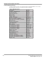
 Table 7  Replacement parts ......................................................................................................... 18

Figures

Figure 1  

Mounting Bracket Installation ......................................................................................... 9

Figure 2  Rear View of PA300 ....................................................................................................... 10
Figure 3  Control Cable Wiring Diagram ..................................................................................... 11
Figure 4  Horn Ring Connections ................................................................................................ 11

Figure 5  Press-and-Hold Modification - Factory Configuration

 ............................................... 13

Figure 6  Press-and-Hold Modification - Air Horn Configuration

 .............................................. 14

Figure 7  Relative PA Loudness ................................................................................................... 14
Figure 8  Front View ...................................................................................................................... 15
Figure 9  Internal View .................................................................................................................. 19

Contents

Safety Messages for Installers and Operators ............................................................................. 4
Overview........................................................................................................................................... 7
Unpacking ........................................................................................................................................ 8
Installation ........................................................................................................................................ 9
Testing the Installation .................................................................................................................. 15
Operating the Unit ......................................................................................................................... 15
Getting Technical Support and Service ....................................................................................... 17

Содержание PA300 Series 690009

Страница 1: ...Model PA300 Series Electronic Siren Models 690000 690001 690002 690004 2561788A Rev A3 0520 Copyright 2004 2020 Federal Signal Corporation Installation and Instruction Manual ...

Страница 2: ...com or call 1 708 534 3400 This limited warranty is in lieu of all other warranties express or implied contractual or statutory including but not limited to the warranty of merchantability warranty of fitness for a particular purpose and any warranty against failure of its essential purpose 2645 Federal Signal Drive University Park Illinois 60484 3167 www fedsig com Customer Support Police Fire EM...

Страница 3: ...Figure 1 Mounting Bracket Installation 9 Figure 2 Rear View of PA300 10 Figure 3 Control Cable Wiring Diagram 11 Figure 4 Horn Ring Connections 11 Figure 5 Press and Hold Modification Factory Configuration 13 Figure 6 Press and Hold Modification Air Horn Configuration 14 Figure 7 Relative PA Loudness 14 Figure 8 Front View 15 Figure 9 Internal View 19 Contents Safety Messages for Installers and Op...

Страница 4: ...ways refer to the vehicle s service manuals when performing equipment installations on a vehicle Sound Hazards Your hearing and the hearing of others in or close to your emergency vehicle could be damaged by loud sounds This can occur from short exposures to very loud sounds or from longer exposures to moderately loud sounds For hearing conservation guidance refer to federal state or local recomme...

Страница 5: ...ning others Sound propagation and warning effectiveness will be severely reduced if the speaker is not facing forward Carefully follow the installation instructions and always install the speaker with the projector facing forward Do NOT install the speaker s or route the speaker wires where they may interfere with the operation of airbag sensors Installation of two speakers requires wiring speaker...

Страница 6: ...e the system control while driving in a hazardous situation Although your warning system is operating properly it may not be completely effective People may not see or heed your warning signal You must recognize this fact and continue to drive cautiously Situations may occur that obstruct your warning signal when natural and manmade objects are between your vehicle and others such as raising your ...

Страница 7: ...dditional cables are required Models 690001 and 690004 are supplied with a microphone jack To use the PA functions order the optional Model MNCT SC microphone The Model PA300 Series can drive one 11 ohm impedance high power 100 W or low power 58 W speaker The Tap II feature enables the driver to change the siren sound from wail to yelp or vice versa via the vehicle s horn ring Tap II provides espe...

Страница 8: ... Harmonic Audio Distortion 300 Hz to 3 000 Hz 10 max all power levels from 1 2 to 50 W frequency response 3 dB Input Impedance Radio 2000 ohms Input voltage required to obtain 20 VRMS across speaker load Radio 0 3 VRMS Unpacking After unpacking the Model PA300 Series examine it for damage that may have occurred in transit If it has been damaged do not attempt to install or operate it File a claim ...

Страница 9: ...g to the underside of the dash Positioning the bracket below the unit permits mounting on any horizontal surface The unit should be mounted in a position that is both comfortable and convenient to the operator Keep visibility and accessibility of controls in mind See Figure 1 Figure 1 Mounting Bracket Installation L 290A4452 02 NOTE Only one bracket is supplied 1 4 20 X 1 2 in Hex Hd Cap Screw 1 4...

Страница 10: ...sition marks 3 Secure the mounting bracket to the dash with user supplied 1 4 20 by 3 4 inch hex head screws 1 4 inch split lockwashers and 1 4 20 hex nuts as shown in Figure 1 4 Secure the electronic siren to the mounting bracket with 1 4 20 by 1 2 inch hex head screws and 1 4 inch split lockwashers as shown in Figure 1 To avoid damage to the unit the 1 4 20 by 1 2 inch hex head cap screws and th...

Страница 11: ...io Brn Non ribbed Radio Zip Cord 8 9 5 4 2 1 Blu Spkr Com 7 1 2 3 4 5 6 7 8 9 10 Red Power Blk Ground 290A4452 04C Radio To allow incoming radio messages to be rebroadcast over the outside speakers connect the two brown zip cord leads pins 1 and 2 across the two way radio s speaker Horn Ring To use the siren s Tap II and Press and Hold features 1 Locate the wire that connects the vehicle horn ring...

Страница 12: ...the other end of the relay coil to the opposite potential of that connected to the wiper in step 8 Connecting to the Power Source PROPER FUSING To avoid damage to unit ensure that it is properly fused with an 20 A in line fuse and fuseholder installed in the red power cable lead The PA300 Series can operate only from a 12 volt negative ground vehicle electrical system Therefore before making any e...

Страница 13: ...l fires and molten metal Verify that no short circuits exist before connecting to the positive battery terminal FIRE HAZARD DO NOT connect this system to the vehicle battery until ALL other electrical connections are made and mounting of all components is complete Failure to observe this warning may result in fire burns and blindness 3 Connect the in line fuseholder lead to the positive battery te...

Страница 14: ...one push to talk switch speak in a normal voice and adjust the GAIN control for the desired sound level outside the vehicle Turn on the vehicle s two way radio and adjust the volume to a comfortable listening level inside the vehicle Then set the Selector switch to RADIO Stand outside of the vehicle and note the radio rebroadcast loudness If the sound volume is too loud or too soft using a small f...

Страница 15: ...reproduction in the public address mode The microphone push to talk switch will override all siren functions except radio rebroadcast for instant PA use Gain Control The GAIN control is used to turn the siren on and off It is also used to control the volume when the siren is used for public address or radio amplification Clockwise rotation of the knob increases voice volume in the public address o...

Страница 16: ...d will be heard This distinctive tone may be reserved for any special indication or situation Priority Models 690002 and 690004 In this position a rapid YELP sound will be heard This distinctive tone may be reserved for any special indication or situation Horn Siren Switch The HORN SIREN switch located on the left side of the front panel activates the electronic air horn sound up or peak and hold ...

Страница 17: ...es Release of Horn Ring Produces Priority Air Horn Priority Manual Peak and Hold or Air Horn Coast Down and Silence or Silence Getting Technical Support and Service For technical support and service please contact Service Department Federal Signal Corporation Phone 1 800 433 9132 Email empserviceinfo fedsig com www fedsig com Getting Repair Service The Federal Signal factory provides technical ass...

Страница 18: ...h Toggle 122377 Header 10 Pole Molex 140454 05 Microphone 690000 and 690002 258B577 03 Optional Microphone 690001 and 690004 MNCT SC Microphone Clip 85361082 Microphone Strain Relief 231A148 Knob Gain Control 141A102 Knob Selector 141A111 Circuit Board Assy 690000 2005183 1234 Circuit Board Assy 690001 2005183 123 Circuit Board Assy 690002 2005183 124 Circuit Board Assy 690004 2005183 134 Switch G...

Страница 19: ...Figure 9 Internal View 290a4452 10 Microphone Toggle Switch Selector Knob Gain Control Knob Gain Control Faceplate Logo Faceplate Rotary Switch Output Transistor Output Transistor Output Transformer ...

Страница 20: ...al Signal Drive University Park Illinois 60484 3167 www fedsig com Customer Support Police Fire EMS 800 264 3578 1 708 534 3400 Work Truck 800 824 0254 1 708 534 3400 Technical Support 800 433 9132 1 708 534 3400 ...

Отзывы: