Installation and Service Instructions
6
Closing the Housing
4. Verify that the cover gasket is in the groove around the perimeter of the
cover.
5. Align the housing with the cover. Note that the FS logo on the front of the
eHorn-HV needs to be oriented correctly with the arrow on the inside of the
cover or the two parts will not fit together.
6. See Figure 3 for bracket assembly instructions.
7. Tighten the cover screws hand tight, then torque them to 60 in-lb ± 10 in-lb.
Wiring the eHorn-HV
SHOCK HAZARD: To avoid electrical shock, do not connect
wires when the circuits are energized.
The external leads and connector must be suitably protected to prevent damage.
Use grommets, bushings, and wires ties to protect them from abrasion. The horn
is provided with 12” 14AWG wire leads with an Aptiv (Delphi) 2P male connector
(Aptiv p/n 12010973) for customer connection. Wire polarity is as follows: red +
(positive), black - (negative).
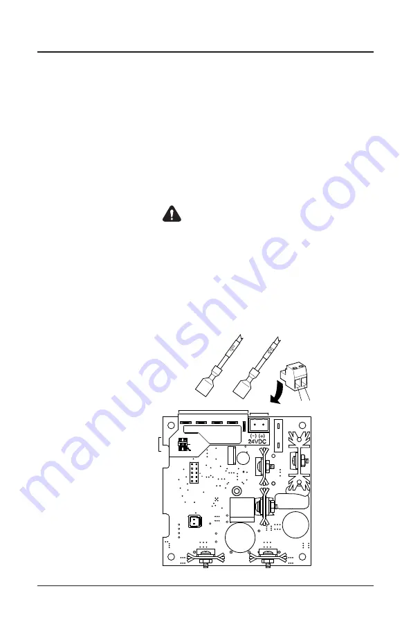
Figure 5
Tone Generator/
Amplifier Board
See installation manual or
the product cover
for tap settings
Tone
Selection
P1
P3
P4 P5
1
2
DC
Power
DC Power
Connector
Input
Power
Tap
Wires
(-)
(+)
P2
Power Taps
52
55/56
7.5


