Federal Signal Corporation Commander 371ST-250, Руководство по установке и обслуживанию
Компания Federal Signal Corporation представляет командный сигнал Commander 371ST-250, предназначенный для установки и обслуживания аварийных ситуаций. Вы можете бесплатно скачать руководство по установке и обслуживанию на нашем сайте. Не забудьте загрузить его с manualshive.com.
Поделиться
Скачать


Отзывы:
Нет отзывов
Похожие инструкции для Commander 371ST-250

3330
Бренд: Keithley Страницы: 149

Ares
Бренд: CAE Healthcare Страницы: 108

CT-1000
Бренд: Cannon Страницы: 36

POWER CLEAN
Бренд: Macht Dental Страницы: 8

RT60
Бренд: Qu-Bit Electronix Страницы: 15

Neon Series
Бренд: Ultrawave Страницы: 30

PD1 series
Бренд: Ultrasound Technologies Страницы: 12
MIC4000P
Бренд: UFO Страницы: 12

AP 2
Бренд: Pani Страницы: 12

1579
Бренд: FASTER TOOLS Страницы: 19

Maxedia 4
Бренд: Martin Страницы: 202

2261998USBA1-XX
Бренд: MMF POS Страницы: 5

Powerbase S8
Бренд: Irwin Страницы: 2

HT588579
Бренд: ABB Страницы: 136

HT598319
Бренд: ABB Страницы: 108

Optima LE-80K
Бренд: Beckman Coulter Страницы: 52

Royal RC005
Бренд: Copernicus Страницы: 13
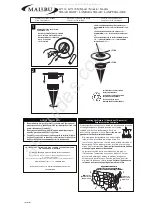
Malibu LZ312
Бренд: Intermatic Страницы: 2


